| |
Hi, I am a newbie and would appreciate some help. My 11 year old has just
joined his school robotics club. He will be using set 9794 (Mindstorms for
School with ROBOLAB 2.5.4) and has to prepare a robot for a Tug-of-War
competition (based on FLL rules) in just 2 weeks time. This is really short
notice! I have
downloaded various pdf files from the net (artoflego, FLL guides etc.) as
well as buying a digital copy of the Ferraris' book. I am at a loss as to
how to help him beyond attempting to digest all this downloaded material as
fast as I can. Any suggestions?
Thanks in advance,
Raj.
|
|
| |
On Sun, June 4, 2006 9:22 pm, raj wrote:
> Hi, I am a newbie and would appreciate some help. My 11 year old has just
> joined his school robotics club. He will be using set 9794 (Mindstorms for
> School with ROBOLAB 2.5.4) and has to prepare a robot for a Tug-of-War
> competition (based on FLL rules) in just 2 weeks time. This is really short
> notice! I have
> downloaded various pdf files from the net (artoflego, FLL guides etc.) as
> well as buying a digital copy of the Ferraris' book. I am at a loss as to
> how to help him beyond attempting to digest all this downloaded material as
> fast as I can. Any suggestions?
> Thanks in advance,
> Raj.
Raj
One major key to making a good Tug-of-War robot will be making it go the "right"
speed. If it goes too fast, some of the "power" will be wasted on speed. If it
goes too slow, it won't use all the power it has.
To change the speed of the robot, adjust the size of the wheels, and/or the gearing
between the motors & wheels.
When you hold the robot in place, the wheels should still spin. If they don't, the
robot is too fast. It's harder to tell if the robot is too slow.
The "right" speed will change with the weight of the robot, and the surface it's
driving on. You should find out what surface will be used, and have your son do as
much testing as possible to find the best speed.
That's a crash course. Good luck... :)
Questions?
Steve
|
|
| |
> One major key to making a good Tug-of-War robot will be making it go the
> "right"speed. If it goes too fast, some of the "power" will be wasted on
> speed. If it goes too slow, it won't use all the power it has.
> To change the speed of the robot, adjust the size of the wheels, and/or the
> gearing between the motors & wheels.
> When you hold the robot in place, the wheels should still spin. If they
> don't, the robot is too fast. It's harder to tell if the robot is too slow.
> The "right" speed will change with the weight of the robot, and the surface
> it's driving on. You should find out what surface will be used, and have
> your son do as much testing as possible to find the best speed.
> That's a crash course. Good luck... :)
> Questions?
> Steve
Steve,
Thanks for the tips and good wishes. Currently this is what we have:
- 3 wheels driven by 3 motors. Each geared down at 15:1
- the wheels do keep spinning when the robot is held in place
- very generous size limit, a 250mm cube - so no problem there
- weight limit is imposed indirectly by being limited to one set of 9794
Problems/questions:
- even after 'loading' the robot with the entire set (IR tower too!), there
is insufficient weight for the torque available. No way around this is
there?
- roughly at what gearing ratio are you at risk of breaking gears and axles?
FLL literature mentions 125:1 as probably too much. What would be 'extreme'
and still safe?
Raj
|
|
| |
On Mon, June 5, 2006 12:47 pm, raj wrote:
> > One major key to making a good Tug-of-War robot will be making it go the
> > "right"speed.
>
> - the wheels do keep spinning when the robot is held in place
> - weight limit is imposed indirectly by being limited to one set of 9794
>
> Problems/questions:
> - even after 'loading' the robot with the entire set (IR tower too!), there
> is insufficient weight for the torque available. No way around this is
> there?
> - roughly at what gearing ratio are you at risk of breaking gears and axles?
> FLL literature mentions 125:1 as probably too much. What would be 'extreme'
> and still safe?
I suspect you're far from breaking gears or axles. However, keep in mind it is
always possible (so don't blame me if it happens) :) Keep the distance between
gears & wheels small, so the axles don't twist.
Sounds like you still have more torque that you are using. (the wheels are
spinning) So, you don't need to gear it down anymore. That will just give you MORE
torque.
You can (A) add more weight (B) make it go faster, or (C) add more traction.
Considering you're already at the weight limit (out of parts), option (A) is out.
Making it go faster is a reasonable option. Geared down 5:1 should still work,
depending on the wheels.
Adding more traction would mean using more wheels. It's likely you're out of
wheels, because there are only 3 wheels in a couple types in the RIS kit. So,
you're best option would be to increase the speed.
Also, it sounds like you can really start doing some testing. Use some string or
something, and have the robot drag books across the table. See how changing things
will make a difference in the weight of the books it can move.
Finally, remember, you can mechanically connect all the motors together, so they are
driving the same wheels. This assures all wheels are getting the maximum amount of
power.
BTW, don't use tank treads.
Steve
|
|
| |
raj wrote:
> Problems/questions:
> - even after 'loading' the robot with the entire set (IR tower too!), there
> is insufficient weight for the torque available. No way around this is
> there?
Well, I'm not exactly an expert - but it seems to me (if the rules allow
it) that attaching the tow rope above the center of gravity of the robot
and putting the drive wheels at the end nearest your opponent would
result in the force of your opponent's pulling being transferred to
the drive wheels of the robot.
> - roughly at what gearing ratio are you at risk of breaking gears and axles?
> FLL literature mentions 125:1 as probably too much. What would be 'extreme'
> and still safe?
I'd guess they are about right - I've geared things up to around that
range and twisted axles.
Also - there starts to become a definite safety risk - you don't want to
get your kids fingers into anywhere with that amount of torque!
It seems odd that you could build something really dangerous out of Lego
but it's definitely possible when you start gearing things down that
much!
|
|
| |
Steve Hassenplug wrote:
> You can (A) add more weight (B) make it go faster, or (C) add more
traction.
> Considering you're already at the weight limit (out of parts), option
(A) is out.
>
> Making it go faster is a reasonable option. Geared down 5:1 should
still work,
> depending on the wheels.
>
> Adding more traction would mean using more wheels. It's likely
you're out of
> wheels, because there are only 3 wheels in a couple types in the RIS
kit. So,
> you're best option would be to increase the speed.
I guess a little sophistication might help traction.
(This is a little 'out there' - but maybe worth investigation)
Lego tyres and tracks are made of rubber - and presuming things work in
a similar way at the scale of Lego as they do at the scale of a full
sized car, there is the matter of sliding friction versus static
friction to consider.
Your car has probably has antilock brakes that make sure that the wheels
roll along the road rather than slipping when you brake hard. That's
because the coefficient of friction of rubber is much higher when it's
not slipping than when it is.
In the case of a tug of war, that would mean that you want to prevent
the wheels from spinning faster than the robot is proceeding across the
ground.
One way to measure that would be with a pair of rotation sensors (which
I presume you don't have - but bear with me). If you hade one wheel
connected to a rotation sensor but nothing else and another sensor on
one of your driven wheels then in theory you could compare their speeds
and if the driven wheel is going slower than the idler then you don't
have maximum friction because it's slipping and giving it a little less
power for a while might help.
Since you don't have a rotation sensor in the basic RCX kit, you have
to improvise. One approach is to use a switch to count revolutions of
a shaft with some sort of protusion that presses the switch once each
revolution - however that obstructs things and eats some power.
Using the light sensor with black and white bricks fixed to the shaft
is another way - that doesn't put a load on the shaft - which is nice,
but you only have one and it looks like you need two. Here is the
next trick - connect a differential gearbox between the idle wheel and
the driven wheel. The output shaft can be set up so it doesn't
rotate when the two wheels are moving at the same speed and it does
rotate when one of them is slipping. Hence you can simply look at
the output of the differential to let the RCX know whether the
driven wheels are slipping and adjust motor speeds accordingly.
I suspect it'll take a lot of work to actually make this work nicely.
|
|
| |
> So, you're best option would be to increase the speed.
> Finally, remember, you can mechanically connect all the motors together, so
> they are driving the same wheels. This assures all wheels are getting the
> maximum amount of power.
Steve,
Philo's page on 'Wheels, Tyres & Traction' seems to imply that increased
speed will not make much of a difference or am I reading that wrong?
By 'mechanically connect' do you mean by using two differentials?
The maximum 'safe' gearing down ratio was a general question. I was hoping
for an answer like 'anything below 100:1 is fine'.
Raj
|
|
| |
> Well, I'm not exactly an expert - but it seems to me (if the rules allow
> it) that attaching the tow rope above the center of gravity of the robot
> and putting the drive wheels at the end nearest your opponent would
> result in the force of your opponent's pulling being transferred to
> the drive wheels of the robot.
Steve,
Provided that my robot doesn't tip-over and that only the front
wheels are driven. I have seen a video of a robot in last year's
competition that opened up into a V-shape. The angle between the arms
of the V being greater than 90 degrees. One arm attached to the tow
rope and the other heavier arm counterbalancing it, forcing all the
weight of the robot to be borne by two small, mightily geared down
wheels that were at the apex of the V. Really cool but way beyond
my current abilities!
Raj
|
|
| |
> Steve Hassenplug wrote:
>
> I guess a little sophistication might help traction.
Steve,
One rotation sensor is allowed. There are also two light sensors,
so your idea is definitely doable.
The situations that are confusing are when the pull of the other
robot prevents your robot from making any headway, as well as when
your robot is actually being pulled back. Are you suggesting that in
these situations it would be better if the wheels are stationary and
locked as opposed to slipping as they keep spinning ? My physics is
is definitely not up to this task - lol.
Raj
|
|
| |
In lugnet.robotics, Rajinder Dhillon wrote:
> > So, you're best option would be to increase the speed.
>
> > Finally, remember, you can mechanically connect all the motors together, so
> > they are driving the same wheels. This assures all wheels are getting the
> > maximum amount of power.
>
> Steve,
>
> Philo's page on 'Wheels, Tyres & Traction' seems to imply that increased
> speed will not make much of a difference or am I reading that wrong?
>
> By 'mechanically connect' do you mean by using two differentials?
>
> The maximum 'safe' gearing down ratio was a general question. I was hoping
> for an answer like 'anything below 100:1 is fine'.
>
> Raj
One rotation sensor and a differential will allow you to compare the rotation of
two wheels. If the driven wheel and the undriven wheel come in the two sides of
the differential, and the rotation sensor is connected to the drive ring, then
the rotation sensor will only rotate if the wheels are going different speeds.
In theory, you should be able to tell forward slip from the backward slip of
being pulled by the other bot. In theory. I haven't tried it.
Note that on farm tractors the drawbar height is lower than the height of the
rear axle, so that the pull of the tool creates less lifting torque on the front
end. Also, note that the net torque is *always* trying to lift the front end,
even with the drawbar below the axle. The rotation point of the torque is the
tire/ground contact point, *not* the axle. The lifting torque on the front end
will be proportional to the distance between the drawbar and the ground, *not*
the distance between the drawbar and the axle. You want to maximize the weight
to the front. In farm tractors, there is a a bracket on the front end that
allows you to add weights.
-dave
|
|
| |
You only need one rotation sensor and some fancy gearing. Using a differential
in a way similar to the "South Facing Cart" or the stearing drive in a dual
differential setup, you could directly measure the amount of spin between a
driven wheel and an idler wheel (a wheel not attached to the motors that turns
when your robot moves forward or backward).
In this kind of configuration, the differential is stationary when the drive
wheels and idler wheel turn at the same speed in the same direction. When the
drive wheels slip, the differential will rotate. You could write your program
to lower motor power whenever the differential starts to turn (indicating that
wheel slip is occurring), and slowly raise the motor power while the
differential is stationary. Locking the wheels is never a good idea.
This may give your robot a big "OOOHHH" factor, but you will get a much bigger
return from playing around with the tow rope. If it is legal,try to design
something that raises your end of the tow rope above your oponent's end. Then
the act of pulling exerts a downward force on your robot and an upward force on
your opponent's.
|
|
| |
In lugnet.robotics, Dean Hystad wrote:
> If it is legal,try to design
> something that raises your end of the tow rope above your oponent's end. Then
> the act of pulling exerts a downward force on your robot and an upward force on
> your opponent's.
Ummm.... that's not the way I remember the mechanics. There is a torque created
that is force on the drawbar times the drawbar height from ground. That torque
will lift your front end. Doubling your own drawbar height halves your pulling
ability before your front end lifts.
-dave
|
|
| |
Dean Hystad wrote:
> This may give your robot a big "OOOHHH" factor, but you will get a much bigger
> return from playing around with the tow rope. If it is legal,try to design
> something that raises your end of the tow rope above your oponent's end. Then
> the act of pulling exerts a downward force on your robot and an upward force
> on your opponent's.
Dean,
Thank you for your response. I am going to get on with the tow rope suggestion
right away.
You might like to know that your 2002 'Building Lego Robots for FLL' guide
was the first thing that I read.
Raj
|
|
| |
In lugnet.robotics, Rajinder Dhillon wrote:
> > Steve Hassenplug wrote:
> >
> > I guess a little sophistication might help traction.
>
> Steve,
>
> One rotation sensor is allowed. There are also two light sensors,
> so your idea is definitely doable.
>
> The situations that are confusing are when the pull of the other
> robot prevents your robot from making any headway, as well as when
> your robot is actually being pulled back. Are you suggesting that in
> these situations it would be better if the wheels are stationary and
> locked as opposed to slipping as they keep spinning ? My physics is
> is definitely not up to this task - lol.
Raj,
There's a bit of confusion here. I believe the above quote actually came from
Steve Baker (posting only as Steve).
As Steve Baker pointed out, there is a difference between kinetic (sliding)
friction and static friction. (http://en.wikipedia.org/wiki/Friction) In the
past, I've spent time trying to identify the best approach for things like this
and LEGO sumo. It's difficult to find people who agree on what's best.
All the physics for this begin to get messy when you start talking about kinetic
friction, so, my suggestion is to do some testing yourself.
In my opinion, you want the wheels to go as fast as they can, without stalling
the motor. If two robots are pulling each other, I assume all wheels will be
sliding. That being the case, I'd want mine spinning as fast as possible.
Steve (Hassenplug)
|
|
| |
Some varied thoughts here:
> One rotation sensor and a differential will allow you to compare the rotation of
> two wheels. If the driven wheel and the undriven wheel come in the two sides of
> the differential, and the rotation sensor is connected to the drive ring, then
> the rotation sensor will only rotate if the wheels are going different speeds.
> In theory, you should be able to tell forward slip from the backward slip of
> being pulled by the other bot. In theory. I haven't tried it.
I might be wrong, but my understanding of the Lego differential gearing
is that if both shafts are turning at the same rate and direction, the outer
gear/shell will turn at the same rate as the axles. Only when the two shafts
are turning in opposite directions at equal rates will the outer gear stand still.
> > Finally, remember, you can mechanically connect all the motors together, so
> > they are driving the same wheels. This assures all wheels are getting the
> > maximum amount of power.
Putting two standard gear motors on one RCX output port will increase the
combined output to approximately 1.4 times a single motor. The RCX does
not supply enought current to handle a stall condition of two motors on one
port. RCX output =~ 500 ma Motor stall current =~ 350+ ma
|
|
| |
raj wrote:
> > So, you're best option would be to increase the speed.
>
>
> > Finally, remember, you can mechanically connect all the motors together, so
> > they are driving the same wheels. This assures all wheels are getting the
> > maximum amount of power.
>
>
> Steve,
>
> Philo's page on 'Wheels, Tyres & Traction' seems to imply that increased
> speed will not make much of a difference or am I reading that wrong?
What I'm saying is that if the robot is moving along at (say) 3 inches
per second - then the drive wheels will get most traction if they are
turning at a speed equivelent to 3 inches per second. If they are
rotating faster than that (because the wheels are slipping) then you'll
have less traction than you could if you slowed them down to the
'correct' speed.
> By 'mechanically connect' do you mean by using two differentials?
There are lots of designs for gearing that do this. The idea is to
subtract the rotational speed of one wheel from the rotational speed of
the other - so you have an axle that rotates only when the two wheels
are moving at different speeds. If one wheel is driven and the other
is just idling then the difference in their speeds tells you how much
the driven wheel is slipping. The classical design for this is the
'South pointing chariot' (said to have been invented by the Chinese
4600 years ago!)
http://www.odts.de/southptr/
> The maximum 'safe' gearing down ratio was a general question. I was hoping
> for an answer like 'anything below 100:1 is fine'.
There are too many variables - as someone else pointed out - the
distance along the axle between the driven gear and the wheel
(or whatever) has a big effect. I don't know whether there is a good
rule of thumb - but I do know that I've destroyed axles at gearings
up in the hundred and fifty to one range - so it's definitely a
consideration - but it's not just about gearing - the resistance to
turning of the final output is important too.
So I don't have a good answer for you.
|
|
| |
Mr S wrote:
> I might be wrong, but my understanding of the Lego differential gearing
> is that if both shafts are turning at the same rate and direction, the outer
> gear/shell will turn at the same rate as the axles. Only when the two shafts
> are turning in opposite directions at equal rates will the outer gear stand still.
I think you need another pair of gears on one of the wheels to reverse
its direction.
If you are going to use a rotation sensor to measure the slippage then
you need to realise that the sensor is notoriously poor at very low
speeds. You'll at least want to gear up the difference output shaft
in order to make your slippage sensor more sensitive.
Personally, I'd still use a light sensor since you only really care that
you're slipping - not by how much.
|
|
| |
In lugnet.robotics, Mr S <szinn_the1@yahoo.com> wrote:
> Some varied thoughts here:
>
>
> > One rotation sensor and a differential will allow you to compare the rotation of
> > two wheels. If the driven wheel and the undriven wheel come in the two sides of
> > the differential, and the rotation sensor is connected to the drive ring, then
> > the rotation sensor will only rotate if the wheels are going different speeds.
> > In theory, you should be able to tell forward slip from the backward slip of
> > being pulled by the other bot. In theory. I haven't tried it.
>
> I might be wrong, but my understanding of the Lego differential gearing
> is that if both shafts are turning at the same rate and direction, the outer
> gear/shell will turn at the same rate as the axles. Only when the two shafts
> are turning in opposite directions at equal rates will the outer gear stand still.
Quite true. My bad.
-dave
|
|
| |
In lugnet.robotics, Dave Curtis wrote:
> > something that raises your end of the tow rope above your
> > oponent's end. Then the act of pulling exerts a downward
> > force on your robot and an upward force on your opponent's.
>
> Ummm.... that's not the way I remember the mechanics. There
> is a torque created that is force on the drawbar times the
> drawbar height from ground.
I don't think Dean was talking about torque from the rope tipping the robot;
I think he was talking about the fact that a raised attachment point for the
rope can result in a downward component of the tension, increasing the force
down on the robot and thus potentially increasing the force of friction.
> That torque will lift your front end.
The torque from the rope tension can certainly reduce the downward force at
one end of the vehicle, but it can increase it at the other - you want the
driven wheels where the downward force is increased.
I can do the force analysis - but in the end, you try a bunch of ideas to see
what works. There's a reason you don't employ a physicist as an engineer.
--
Brian Davis
|
|
| |
In lugnet.robotics, Brian Davis wrote:
> In lugnet.robotics, Dave Curtis wrote:
>
> > > something that raises your end of the tow rope above your
> > > oponent's end. Then the act of pulling exerts a downward
> > > force on your robot and an upward force on your opponent's.
> >
> > Ummm.... that's not the way I remember the mechanics. There
> > is a torque created that is force on the drawbar times the
> > drawbar height from ground.
>
> I don't think Dean was talking about torque from the rope tipping the robot;
> I think he was talking about the fact that a raised attachment point for the
> rope can result in a downward component of the tension, increasing the force
> down on the robot and thus potentially increasing the force of friction.
Sure, I understand the argument. But this old farm boy has both a few hours in
the driver's seat of a farm tractor, as well as a couple of engineering degrees,
both of which prompted my cautionary statements. Let me start by saying that I
agree whole-heartedly with you that experimental results trump paper analysis
every time. That said, here is some paper analysis :-)
+-+
|L+----Drawbar <--force L---
+-+
_______Ground____ --force T-->
(wheel and axle not shown, because my ASCII art isn't that good. sorry.)
There is a force L in the -X direction that is the pull of the load on the
drawbar.
There is a force T in the +X direction that is the traction of the wheel against
the ground.
To the extent that T > L, your tractor+load system accelerates to the right.
(F=MA and all that jazz...)
There is a torque of L times the distance from drawbar to ground that wants to
lift the front end. All I'm saying is that raising the drawbar increases that
torque. Now, if the load connector from drawbar to load is at an angle, there
is a Y component to the force, yup, that's true. How does it impact your own
traction versus the other guy's traction? Hmmmm... ??? Time to head for the
workbench.
I'm not looking for an argument, I'm just cautioning that in a tractor+load
situation the above mentioned torque is a significant design challenge, and
anything that makes it worse needs to be well tested. In a farm tractor,
getting a "light front end" means loss of control... I can attest that this
causes the operator some amount of mental discomfort. A robot, OTOH, may not
care if the front end comes off the ground, so long as you can drag your
opponent across the finish line.
>
> > That torque will lift your front end.
>
> The torque from the rope tension can certainly reduce the downward force at
> one end of the vehicle, but it can increase it at the other - you want the
> driven wheels where the downward force is increased.
The farm tractor solution is: 1) low drawbar, 2) long chassis, 3) as much weight
forward as possible. Without going through the analysis, my guess is that
getting the weight forward will be a bigger contributor to traction than you
could get by using your opponent's weight to pull your own back end down.
By now, the original poster is probably sorry he asked :-) I'm certainly not
sorry he asked, this has been fun to think about.
-dave
|
|
| |
Brian Davis wrote:
> I can do the force analysis - but in the end, you try a bunch of ideas to see
> what works. There's a reason you don't employ a physicist as an engineer.
(Or vice-versa!)
|
|
| |
Dave Curtis wrote:
> There is a torque of L times the distance from drawbar to ground that wants to
> lift the front end. All I'm saying is that raising the drawbar increases that
> torque.
Yeah - bad for a tractor with front-wheel steering - and a need to steer
- not so bad for a robot with either no steering or rear-wheel skid
steering.
This robot really doesn't care if it's front end gets light - but for a
tractor it's a major disaster.
But the other major difference is that we're pulling the other robot
via a flexible rope - the only forces are along the line of the rope.
With a tractor and trailer, the trailer pushes down vertically onto
the tow bar as well as being a rearward drag on forward progress.
That also drives the tractor design in directions that aren't
necessarily appropriate for a tug-o-war robot.
> The farm tractor solution is: 1) low drawbar, 2) long chassis, 3) as much weight
> forward as possible. Without going through the analysis, my guess is that
> getting the weight forward will be a bigger contributor to traction than you
> could get by using your opponent's weight to pull your own back end down.
I disagree - friction (for static and dynamic friction) is proportional
to the downforce on the wheels. More friction with the ground is more
traction.
Why waste our limited weight budget weighing down wheels that aren't
generating any traction? (Presuming we aren't concerned about steering
by turning the idle wheels).
Better still is if we can redirect some of the backwards force generated
by your opponent into pushing the wheels harder against the ground by
moving the rope attachment point.
You don't do that on tractors because roll-over accidents on sloping
ground are very dangerous - and raising the tow bar above the center
of gravity would make that lethally worse.
> By now, the original poster is probably sorry he asked :-) I'm certainly not
> sorry he asked, this has been fun to think about.
Of course!
|
|
| |
In lugnet.robotics, steve <sjbaker1@airmail.net> wrote:
> Why waste our limited weight budget weighing down wheels that aren't
> generating any traction? (Presuming we aren't concerned about steering
> by turning the idle wheels).
Thought provoking question. It led me to the conclusion that when the bot is
generating it's maximum possible drawbar pull (as limited by the motor and drive
train), the weight on the undriven front wheels (I'm assuming a rear wheel drive
configuration) should be exactly zero. More than zero is weight not being used
to get traction from the rear drive wheels. Less than zero is the front end
lifting case. Exactly zero is optimal. And I think that holds regardless of
drawbar height. Thoughts?
If you buy that, then given that there is a maximum possible weight limit, it
follows that it is possible to get the drawbar too high. The "too high" case is
where we get negative weight on the front wheels at less than drive-train
limited drawbar pull.
Also, consider an opponent with a drawbar higher than ours. He will generate a
lifting force on our drawbar. Assuming our cable attachment point is to the
rear of the tire/ground contact point, the lifting force on our drawbar creates
a torque tending to force our front end down, giving us >0 weight on the front
axle. In that case, we want to move weight backward until we have zero weight on
the front end again. So, now we can compare drawbar heights analytically. Two
bots: Bot A and bot B have identical drawbar pull. Bot A and bot B have
idenitical weight W. Bot A has a higher drawbar than bot B. Therefore, bot B
will optimally place its weight further back. When both bot's A and B have
placed W optimally, who wins? And furthermore, does it depend on cable length,
since that determines the important angles?
-dave
P.S. In my farm tractor analogy, I'm picturing a plow or subsoiler, where the
down force on the drawbar is negligable compared to the force of pulling the
tool through the soil.
|
|
| |
In lugnet.robotics, Mr S szinn_the1@yahoo.com wrote:
| |
The RCX does
not supply enought current to handle a stall condition of two motors on one
port. RCX output =~ 500 ma Motor stall current =~ 350+ ma
|
Actually it does - barely. With the increased current, RCX output voltage drops,
so does motor stall current.
See these compared charts:
Philo
|
|
| |
Philo,
That's interesting, and looks to explain why it is that I've
never been able to observe the RCX output going to thermal
or current protection cutoff?
I've one largish sumo type bulldozer style robot with 4 treads
that can easily push 4-5 times its own weight. I played with it
trying to see what happens when it hits that immovable object
and have never seen the outputs go into cutoff, or failure, though
I did push them to stall conditions with two motors on each. I
half expected to see smoke, but nope, just no go, and immediate
recovery. It pushes far enough to break chains and twist things
up, but I've never seen the outputs cutout as it is rumored they
will.
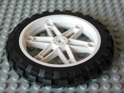
On a side note, your work on testing the motorcycle tires for
traction is of interest to me, and I never got around to asking,
but on a side note here, when you tested this tire
<http://philohome.com/traction/2903.jpg> do you think that the
performace would be improved if the tire were filled with a kind
of PFE tubing (so as to make it a run flat kind of tire) so that it
did not suffer from excessive compression of the rubber tire?
----- Original Message ----
From: Philippe Hurbain <philohome@free.fr>
To: lego-robotics@crynwr.com
Sent: Wednesday, June 7, 2006 1:39:50 AM
Subject: Re: Newbie needs Help (diff sensor)
In lugnet.robotics, Mr S <szinn_the1@yahoo.com> wrote:
> The RCX does
> not supply enought current to handle a stall condition of two motors on one
> port. RCX output =~ 500 ma Motor stall current =~ 350+ ma
Actually it does - barely. With the increased current, RCX output voltage drops,
so does motor stall current.
See these compared charts:
<<http://philohome.com/motors/mechpwr-rcx-2x71427.gif>>
<<http://philohome.com/motors/mechpwr-rcx-71427.gif>>
Philo
|
|
| |
In lugnet.robotics, Mr S <szinn_the1@yahoo.com> wrote:
> Philo,
> That's interesting, and looks to explain why it is that I've
> never been able to observe the RCX output going to thermal
> or current protection cutoff?
It does happen - if you use more that 2 motors or if you try to use a RC motor.
The driver circuit limits current around 500mA, and at that rate it is not long
before going in thermal shutdown mode.
> I did push them to stall conditions with two motors on each. I
> half expected to see smoke,
No, you won't see smoke... RCX motor drivers are very well protected. I never
saw one that failed!
> On a side note, your work on testing the motorcycle tires for
> traction is of interest to me, and I never got around to asking,
> but on a side note here, when you tested this tire
> <http://philohome.com/traction/2903.jpg> do you think that the
> performace would be improved if the tire were filled with a kind
> of PFE tubing (so as to make it a run flat kind of tire) so that it
> did not suffer from excessive compression of the rubber tire?
Honestly I don't know... some more testing would be in order! But it's fairly
hard to control external parameters for that test. As indicated by Steve
somewhere else in that thread, it would be interesting to perform static (no
slip) tests too, but that's even more difficult due to the transient nature just
at the limit...
Philo
>
|
|
| |
In lugnet.robotics, Philippe Hurbain wrote:
> > do you think that the performace would be improved if the
> > tire were filled with a kind of PFE tubing (so as to make
> > it a run flat kind of tire) so that it did not suffer from
> > excessive compression of the rubber tire?
A rather inventive young man that I know did try exactly that - using the
ribbed tubing from the Mindstorms set inside the Mindstorms motorcycle tire.
It's a good fit, and a good idea, but I'm not sure how effective it was.
> it would be interesting to perform static (no slip) tests
> too, but that's even more difficult due to the transient
> nature just at the limit...
One simple way (that honestly doesn't work very well... shows how complex
friction is): the coefficient of friction is just the tangent of the slope angle
when the object "breaks free" and begins sliding down the hill. So you can build
a four-wheeled platform (with the axles locked, so the tires don't turn) and put
it on a board, raising one end of the board until the platform starts sliding.
I've done this, but for various reasons I don't completely trust the results.
It's still interesting and informative, however.
--
Brian Davis
|
|
| |
Mr S wrote:
> On a side note, your work on testing the motorcycle tires for
> traction is of interest to me, and I never got around to asking,
> but on a side note here, when you tested this tire
> <http://philohome.com/traction/2903.jpg> do you think that the
> performace would be improved if the tire were filled with a kind
> of PFE tubing (so as to make it a run flat kind of tire) so that it
> did not suffer from excessive compression of the rubber tire?
I would have expected that compression would be a good thing because
it would increase the area of the 'contact patch' - which increases
traction - which is a good thing - right?
|
|
| |
Brian Davis wrote:
> One simple way (that honestly doesn't work very well... shows how complex
> friction is): the coefficient of friction is just the tangent of the slope angle
> when the object "breaks free" and begins sliding down the hill. So you can build
> a four-wheeled platform (with the axles locked, so the tires don't turn) and put
> it on a board, raising one end of the board until the platform starts sliding.
> I've done this, but for various reasons I don't completely trust the results.
> It's still interesting and informative, however.
The problem is that this is measuring the static friction ("stiction").
That's the wrong thing to measure if your strategy is to jam all the
motors full on and progress forwards (we hope!) with all wheels
spinning.
To measure the dynamic friction ("sliption") you can use the same
locked-up wheel rig and just pull it along flat ground with a
spring balance. Drag it along at a reasonably constant speed
where it isn't jerking along.
So you have two numbers - one for sliption and the other for
stiction. With rubber tyres, those numbers should be very different.
So which one do you want to optimise for? If you have two wheels - one
with great stiction but terrible sliption - and another with
great sliption but poor stiction - which should you choose?
Well - it depends on your strategy.
STRATEGY I:
You plan to drive mindlessly forwards at full speed with all wheels
slipping...several people here have advocated that,
Forget about the results you got for stiction on your inclined
plane - they are quite irrelevent. Look instead at the sliption
figures - your wheels are slipping all the time - so that's the
right number.
Furthermore, realise that the high school physics equations for
sliption say that the frictional force is proportional to the
weight - but NOT related to the contact area. People find that
counter-intuitive - but it's true. So don't bother putting 10
driven wheels on your vehicle - it won't help one bit once you
are out there with all wheels spinning. Tank tracks are useless
for the same reason - they increase the contact area - but if
they are slipping, that's irrelevent.
Stiffer rubber is better because you aren't wasting energy deforming
the rubber in the tyres as they spin and you want to pick the wheel
design with the highest DYNAMIC friction.
STRATEGY II:
You plan to take the slow and steady approach where you don't let
the wheels slip and carefully meter the power to make sure they
aren't slipping. I guess I'd measure the speed difference between
a driven wheel and an idler wheel - then progressively increase
the motor power until the wheel slips - then back off until it
stop slipping - then you can gradually increase power again until
it slips again...just like the ABS in a car.
You'll be taking advantage of that higher stiction coefficient - and
you'll need to be aware that stictional forces ARE proportional to the
contact area...so you want as much rubber in contact with the ground
as possible. Nice fat, soft tyres - the ones that have the highest
stictional coefficient. MAYBE even consider tank tracks IF you
support the bottom of the track with a bunch of little idler wheels.
WHICH APPROACH WORKS BEST?
Well - let's look at some real-world vehicles. My car is a heavily
modified MINI Cooper'S - if I turn off the traction control software
and floor the gas pedal from a dead stop, the wheels will spin like
crazy - there will be tons of smoke and my 0-60 time will be 8 seconds.
If I carefully apply the gas so the wheels don't spin - but are just
on the point where they would if I pushed just a little bit harder -
then my 0-60 time is close to 6 seconds. That's the difference between
stiction and dynamic friction.
Look at a dragster - huge tyres - made of the softest rubber compound,
pre-heated to make them yet softer and run at very low tyre pressure
to keep as much rubber on the ground as possible.
So - *IF* you can manage the mechanical and software sophistication
of measuring and controlling the motors so you apply the maximum
possible power without the wheels slipping - and *IF* the laws of
physics for rubber tyres are similar at the scale of a car versus
a small robot - then going the slow-and-steady route with lots and
lots of big, fat soft tyres should theoretically produce much better
results than just jamming the motors on at full speed.
|
|
| |
> There's a bit of confusion here. I believe the above quote actually came from
> Steve Baker (posting only as Steve).
Steve Hassenplug,
Sorry, my mistake. Thank you for the Wiki link and all your help.
Raj.
|
|
| |
In lugnet.robotics, Dave Curtis wrote:
> By now, the original poster is probably sorry he asked :-) I'm certainly not
> sorry he asked, this has been fun to think about.
Dave,
Actually I am very happy and grateful. I am getting a crash course.
Couldn't have asked for more.
Raj.
|
|
| |
Dave Curtis wrote:
> Thought provoking question. It led me to the conclusion that when the bot is
> generating it's maximum possible drawbar pull (as limited by the motor and drive
> train), the weight on the undriven front wheels (I'm assuming a rear wheel drive
> configuration) should be exactly zero.
That makes sense.
> And I think that holds regardless of drawbar height. Thoughts?
Yeah - I agree.
So we have to sum some force vectors here. If our robot is pulling
to the left, we have a horizontal 'drive' force to the left and a force
in the tow rope going off to the right - plus a force due to gravity due
to the weight of the robot pointing down and a 'reaction force' from the
ground pushing upwards to equalise the total downward force.
All of these sum to produce a net force using the parallelogram rule.
If the tow rope is exactly horizontal - then the force from the drive
wheels has to be larger than the force in rope for you to win. The
weight of the robot and the reaction force are also equal so the amount
of traction we get (which depends on that reaction force) is
proportional to the weight of the robot.
OK - so what happens if the rope isn't horizontal. Suppose our tow
hitch is higher than the opposition and the rope slopes downwards to the
right.
The force due to the rope is now split into two parts. The horizontal
component of the force still has to be counteracted by the pull of the
wheels - and there is a vertical component which ADDS to the weight of
the robot and therefore INCREASES the ground reaction force - thereby
INCREASING the traction you get...which is good!
If the rope slopes upwards, the vertical component of the force is
now pointing upwards - it's reducing the reaction force and reducing
our traction.
If the rope points DOWN for us - it must point UP for our opponent - so
a downward pointing rope is a win/win thing!
However, if you get the rope to slope down by simply attaching it to
the top of the robot instead of the bottom - there are some other
consequences.
Because the force applied by our wheels is acting at the very bottom
of the robot (at ground level) and the horizontal component of the
force due to the rope is pointing in the opposite direction and acting
higher up, we have a 'moment' - a tendancy to turn the robot in a
clockwise direction (remember it's driving to our left).
If the driven wheels are the ones at the back, that moment will
tend to lift the front wheels and there is a risk of our robot
flipping onto it's back.
The trick here is to mount the tow rope on the FRONT of the robot
fairly high up.
If the robot is pulled so hard that the front wheels come off the
ground - then the rope mounting point will go UP in height. That
in turn will increase the downward slope on the rope - and we know
that having a downward slope produces a DOWNWARD force,,,,which
will tend to push the front of the robot back down again.
So a L-O-N-G nose - with the rope attached high at the front
has some interesting possibilities.
> P.S. In my farm tractor analogy, I'm picturing a plow or subsoiler, where the
> down force on the drawbar is negligable compared to the force of pulling the
> tool through the soil.
Ah - OK. Tractor design has to be a compromise between different
kinds of load...the robot can be mindlessly optimised for just
one answer.
|
|
| |
In lugnet.robotics, steve <sjbaker1@airmail.net> wrote:
> [snip description of "tangent board" test to measure static friction]
>
> The problem is that this is measuring the static friction...
As you note in your mini-cooper example, *if* you can keep the wheels from
"spinning out", but instead are always in rolling contact with the ground,
static friction is what's important... and generally, the static coefficient of
friction is larger than the dyanmic coefficient of friction. Ideally, to get the
maximum tension in the rope, you do *not* want your tires to break free. This is
why I brought up this example.
> To measure the dynamic friction you can use the same locked-up
> wheel rig and just pull it along flat ground with a spring
> balance. Drag it along at a reasonably constant speed where it
> isn't jerking along.
That's not very easy in practice, and you need to make sure the rope is
pulled parallel to the floor. I've always wanted to use the RCX and a sensor to
do this automaticly, but the results "by hand" have always been so poor I've
never bothered.
> Furthermore, realise that the high school physics equations for
> sliption say that the frictional force is proportional to the
> weight - but NOT related to the contact area. People find that
> counter-intuitive - but it's true.
It's wonderfully true in the world of high-school physics, but the real world
can be significantly different. Since the behavior of the rubber depends on the
pressure exerted, as well as the dynamic physics of what happens as the tire
repeatedly sticks and slips (both are still occuring), this is another one of
those places where I suggest you do some empirical tests, and not worry too much
about what the physicist say (and for the record, I *am* one of them... I have
great fun in my college level classes showing the students where the textbook
solution fails miserably in the realy world).
> Tank tracks are useless for the same reason - they increase
> the contact area
The problem is, the LEGO tank treads really don't - even if you include a
bunch of idler wheels like on a real tank, take a look at how much of the tread
actually contacts the surface and you'll see what I mean.
> Stiffer rubber is better...
All other things being equal, perhaps... but how "hard" or "soft" the rubber
is plays a major role in the coefficient of friction. "Stiff" tires often have
lower coefficients of friction (both static and dynamic) on certain surfaces...
which brings up another factor that hasn't been mentioned (too much), the fact
that different tires have different coefficients of friction on different
surfaces... and the one that's good on surface A may not be the best on surface
B.
> and you'll need to be aware that stictional forces ARE
> proportional to the contact area...
OK, I'm confused. Why would one of these forces be proportional to the
surface area, and the other not? In both cases, the frictional force is just the
normal force (usually the weight) times the coeffecient of friction. Period.
Surface area (in "textbook" physics) just doesn't enter into it.
> MAYBE even consider tank tracks IF you support the bottom
> of the track with a bunch of little idler wheels.
Only on the right kind of carpet, or maybe mud.
--
Brian Davis
|
|
| |
On Wed, June 7, 2006 12:42 pm, Brian Davis wrote:
> In lugnet.robotics, steve <sjbaker1@airmail.net> wrote:
> > To measure the dynamic friction you can use the same locked-up
> > wheel rig and just pull it along flat ground with a spring
> > balance. Drag it along at a reasonably constant speed where it
> > isn't jerking along.
>
> That's not very easy in practice, and you need to make sure the rope is
> pulled parallel to the floor. I've always wanted to use the RCX and a sensor to
> do this automaticly, but the results "by hand" have always been so poor I've
> never bothered.
hmm. This sounds like a good project...
> > Furthermore, realise that the high school physics equations for
> > sliption say that the frictional force is proportional to the
> > weight - but NOT related to the contact area. People find that
> > counter-intuitive - but it's true.
>
> It's wonderfully true in the world of high-school physics, but the real world
> can be significantly different.
All things being equal, I'd put my money on the robot with ten spinning wheels, over
a couple (or even ten) stationary ones.
I'd also mechanically connect all the motors together, so they drive a single axle
(no differential). But, given three motors, I'd connect them to separate outputs on
the RCX.
I'd find out what type of surface the event will be on, and do as much testing as
possible, to find out what speed will tow the most weight.
Beyond that, there are MANY mechanical things that can be adjusted & changed.
Testing is important.
Good luck, & have fun.
Steve Hassenplug
|
|
| |
Brian Davis wrote:
> > To measure the dynamic friction you can use the same locked-up
> > wheel rig and just pull it along flat ground with a spring
> > balance. Drag it along at a reasonably constant speed where it
> > isn't jerking along.
>
> That's not very easy in practice, and you need to make sure the rope is
> pulled parallel to the floor. I've always wanted to use the RCX and a sensor to
> do this automaticly, but the results "by hand" have always been so poor I've
> never bothered.
Hmmm - that's unfortunate...but if the 'right' strategy is to
go with a non-slipping robot, the measurement of sliption is
really a lot less important.
> > Furthermore, realise that the high school physics equations for
> > sliption say that the frictional force is proportional to the
> > weight - but NOT related to the contact area. People find that
> > counter-intuitive - but it's true.
>
> It's wonderfully true in the world of high-school physics, but the real world
> can be significantly different. Since the behavior of the rubber depends on the
> pressure exerted, as well as the dynamic physics of what happens as the tire
> repeatedly sticks and slips (both are still occuring), this is another one of
> those places where I suggest you do some empirical tests, and not worry too much
> about what the physicist say (and for the record, I *am* one of them... I have
> great fun in my college level classes showing the students where the textbook
> solution fails miserably in the realy world).
Yeah - so many of those basic mechanics equations are only
approximations - yet they are taught as if they were laws.
I enjoyed Richard Feyneman's commentary on this subject.
However, whilst it's not 100% true - it's not such a terrible
approximation. Several people here have noted that adding more
wheels doesn't help.
> > Tank tracks are useless for the same reason - they increase
> > the contact area
>
> The problem is, the LEGO tank treads really don't - even if you include a
> bunch of idler wheels like on a real tank, take a look at how much of the tread
> actually contacts the surface and you'll see what I mean.
Yeah - the ribbing on the track looks to be the problem. A smoother
track would work better. (That's back to having nice knobbly off-road
tyres versus racing slicks).
> > Stiffer rubber is better...
>
> All other things being equal, perhaps... but how "hard" or "soft" the rubber
> is plays a major role in the coefficient of friction. "Stiff" tires often have
> lower coefficients of friction (both static and dynamic) on certain surfaces...
> which brings up another factor that hasn't been mentioned (too much),
Having soft rubber on car tyres eats energy at higher speeds because
energy is absorbed in repeatedly flexing the side-walls of the tyre.
At lower speeds, compressing the sidewalls as the tyre approaches
the ground is kinda like driving uphill...it's generally undesirable
for all kinds of drive - but if your wheels are spinning, that's a
MUCH bigger effect than when they are moving quite slowly.
> > and you'll need to be aware that stictional forces ARE
> > proportional to the contact area...
>
> OK, I'm confused. Why would one of these forces be proportional to the
> surface area, and the other not?
Dunno - I'm happy to defer to your expert knowledge!
> In both cases, the frictional force is just the
> normal force (usually the weight) times the coeffecient of friction. Period.
> Surface area (in "textbook" physics) just doesn't enter into it.
That's certainly not true in reality. Cars with wider tyres grip
better - that's absolutely for sure - using dead smooth racing slicks
gets you better grip (in dry conditions) than tyres with grooves cut
into them...just see the effect on a Formula I race car when the team
guess wrong about the weather and put on the wrong kind of tyre! Both
are made of soft compound rubber - both have about the same contact
patch - but one has a bunch of places where its not touching the ground.
The car weighs the same in both cases...the only difference is the area.
On the other hand, I remember the high school physics class where
we took a heavy wooden block and dragged it along a nice level surface -
noting that it didn't matter whether we put the block on it's big flat
side, it's narrower side or on one end - the frictional force was
the same...so the contact area didn't matter.
I presumed that was because wheels that aren't slipping are reliant
on static friction and that the experiment we did in school was
dynamic friction. Perhaps I came away with the wrong impression
here and the dependence on area depends more on the nature of the
materials involved (rubber is weird stuff).
|
|
| |
In lugnet.robotics, Steve Hassenplug wrote:
> > I've always wanted to use the RCX and a sensor to
> > do this [measure the kinetic coefficient of friction]
> > automaticly...
>
> hmm. This sounds like a good project...
I'll get to that, eventually... there's just too much fun stuff going on,
and...
> All things being equal, I'd put my money on the robot
> with ten spinning wheels, over a couple (or even ten)
> stationary ones.
A historical point on this. The first time I met Steve was at a sumo event,
where I had carefully calculated the correct gear ratio, given the torque of a
motor, and the weight of the robot, and where to put the drive wheels. It was
even for this that I had initially measured the coefficient of static friction.
Steve showed up with a battery-box driven robot that used some unbelievable
number of small wheels, and promptly trashed my "perfected" robot.
Moral: figure all you want. Calculate, measure, and plot. Then TEST.
Testtesttesttest. And when that's done, test some more, in new ways. And when
you're polished robot has passed all those tests with flying colors... give it
to a five-year-old who will likely point out the blind spot you missed in 30
seconds.
> Testing is important.
I think I'd have to agree :-).
--
Brian Davis
|
|
| |
In lugnet.robotics, steve <sjbaker1@airmail.net> wrote:
> Mr S wrote:
>
> > On a side note, your work on testing the motorcycle tires for
> > traction is of interest to me, and I never got around to asking,
> > but on a side note here, when you tested this tire
> > <http://philohome.com/traction/2903.jpg> do you think that the
> > performace would be improved if the tire were filled with a kind
> > of PFE tubing (so as to make it a run flat kind of tire) so that it
> > did not suffer from excessive compression of the rubber tire?
>
> I would have expected that compression would be a good thing because
> it would increase the area of the 'contact patch' - which increases
> traction - which is a good thing - right?
Not so obvious. If you increase the surface the pressure per surface unit
decreases proportionnaly (at least on hard surface)... Actually I would expect
little or no variation in traction power.
Philo
|
|
| |
In lugnet.robotics, steve <sjbaker1@airmail.net> wrote:
> The trick here is to mount the tow rope on the FRONT of the robot
> fairly high up.
> ...
>
> So a L-O-N-G nose - with the rope attached high at the front
> has some interesting possibilities.
I'm with you until we get here. Attaching at the front of a long nose feels
like a bad idea. Any side force on the tow rope will tend to pull the robot off
course, and once slightly off course the force only gets worse. In any case, a
front-end tow rope attachment will want to be routed *under* the chassis and
drive axle, so that the "back flip" case doesn't turn into a spectactular
disaster.
At this point I'm going to quit speculating... I need to draw it out and write
up the equations to see it better. Or better yet, go build something.
-dave
|
|
| |
Steve wrote on Tuesday, June 06, 2006 5:59 PM
<<snip>>
> If you are going to use a rotation sensor to measure the slippage then
> you need to realize that the sensor is notoriously poor at very low
> speeds.
<<snip>>
I think what is really meant is that most RCX firmware implementations
are poor at filtering hardware transient errors. And the Rotation sensor
is very "good" at generating transients at a typical rate of about 0.5%
errors. At very slow speeds, the transient error rate increases
dramatically.
Usually, you get a single transient error. However at very slow speeds,
it's quite possible to get several consecutive faulty transient readings
in a row -- I've seen up to four in a row at very low (about 1 complete
rotation per minute) speeds.
The standard Lego firmware provides no transient filtering. BrickOS
filters single transients but always fails when there are two or more
consecutive transients. The RCX replacement firmware used in Robolab 2.9
is the only RCX firmware that I know that properly handles consecutive
transients.
In the interests of full disclosure, I should mention that I wrote the
Robolab 2.9 RCX firmware.
|
|
|