|
|
|
Gus Jansson / SteerBot |
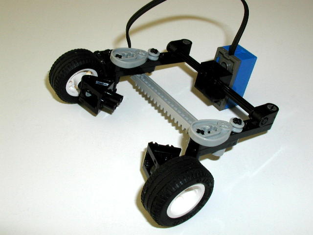
| SteerBot Back to Gus Jansson’s Lego Home Page SteerBot is a robot that drives on a track and steers like a car. It uses two motors, one light sensor, and two touch sensors. One motor drives the back wheels through a standard lego differencial and the other motor steers via a rack and pinion steering. The touch sensors detect steering to full left and full right. The light sensor looks for and tracks the edge between a white and a black region on the surface. 
SteerBot was built for the mini challenge of the first SMART meeting. The challenge was to build a robot that tracks the edge of a wide line. While this robot is designed to track a singe edge, I believe I could convert it to tracking a 3/4” line by adding another light sensor. Click on the photos below to see a larger image.
At the SMART meeting #1 there were several video clips recorded that feature this robot as well as other edge tracking robots. One video of particular interest shows SteerBot passing another one of my edge tracking robots. Video clips from SMART Meeting #1 Edge Tracking Notes The robots basically works by treating the edge as a guide for the steering. The program reads the light sensor and determines which way to run the steering motor to keep the light sensor as centered as possible over the edge. As long as the light sensor is over the edge, the robot can drive forward and the steering will keep it in place. Of course, if the turns are too sharp, then the robot will come off the track. More on this later. In order for this tracking to work, the light sensor needed to be mounted as directly as possible to the motor. In other words, any mechanical slop in between the motor and the light sensor position had to be kept to an absolute minimum. If there is too much slop in the mechanics, then the light sensor would continue to swing past the point of where the steering motor has already turned off. Even if it was possible to have no slop in the mechanics, there is still momentum in the steering parts to contend with. Therefore, when running the steering motor to return the light sensor to the edge, turning off right at the edge is probably too late. The solution to this problem is in the code. The trick here is to get the steering motor to stop even before the light sensor is positioned on the edge. To do that, the robot chooses multiple light threshold values, five in fact, during the initialization. One is the mid point between black and white. The other are two intermediate values on each side of the edge. Think of it as an inner zone and an outer zone around the edge. As long as the light sensor is positioned within the inner zone, then the steering motor is off. If the sensor reading is too dark or bright for the inner zone, then the steering motor is turned on in the direction to bring it back towards the edge. While the steering motor is on, it is kept on until it gets back within the outer zone. If you know what hysteresis is then you will recognize this as a hysteresis with the two thresholds reversed. This has two benefits. First of all, if the sensor just barely gets out of the inner zone, then all you want is a small ‘tap’ to get it back. That is exactly what you get since the steering motor will be turned off immediately after it is turned on since it will still be within the outer zone of the edge. If the light sensor is way off the edge and outside the outer zone, then the steering motor is on until it gets back to the outer zone where it is turned off. If momentum and other factors are not enough to get it to the inner zone then it will be tapped on again until it gets back to the inner zone. The light threshold values that I’m using right now are 25% to 75% of the light range for the outer zone and 37.5% to 62.5% for the inner zone. I always set my light sensors to RAW to get more detail in the light readings. To handle sharp turns the robot keeps track of the time since it last saw the edge. That way, if the robot encounters a turn that is sharper then it can handle, it can begin a 3-point turn manouver. This is done by stopping the edge tracking task, stopping the robot, steer to the opposite full lock, and reverse drive motor to back up a short distance. Afte that it resumes edge tracking. If it still can not find the edge within a certain amount of time, it will do another 3-point turn. The Program SteerBot is programmed in NQC. SteerBot Program |
|
Primary content in this document is © Gus Jansson. All other text, images, or trademarks in this document are the intellectual property of their respective owners. |
| |
©2005 LUGNET. All rights reserved. - hosted by steinbruch.info GbR |