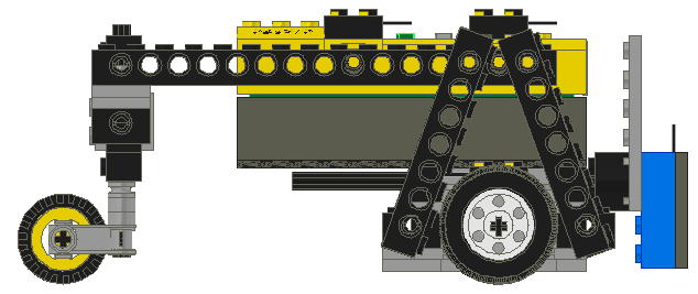
Standard Robot for Workshop 3D RCX Challenge 3
Here are the building instructions for the Standard Robot Line
Tracking event at the Workshop3D RCX Challenge in Seattle on October 6, 2001.
In this event, all competitors’ programs run on identical robots. In addition
to providing the program, the competitor also must specify the desired postion
of the Light Sensor suitable for their program. See more information below.

Qty Color Description
2 Light-Gray Plate 1 x 2 with Door Rail
1 Light-Gray Plate 1 x 10
1 Light-Gray Plate 2 x 10
1 Light-Gray Technic Plate 2 x 6 with Holes
|
|

2 Black Technic Brick 1 x 2 with Hole
1 Black Technic Brick 1 x 8 with Holes
2 Black Technic Pin with Friction
|
|

2 Light-Gray Plate 1 x 2
2 Light-Gray Plate 1 x 2 with Door Rail
|
|

2 Light-Gray Electric Technic Mini-Motor 9v
2 Light-Gray Plate 1 x 2 with Door Rail
1 Light-Gray Plate 1 x 10
|
|

2 Black Technic Brick 1 x 2 with Hole
1 Black Technic Brick 1 x 8 with Holes
2 Black Technic Pin with Friction
|
|

2 Light-Gray Plate 1 x 2
2 Light-Gray Plate 1 x 2 with Door Rail
1 Light-Gray Technic Plate 2 x 6 with Holes
|
|

1 Green Technic Brick 1 x 2 with Axlehole
1 Black Technic Brick 1 x 10 with Holes
|
|

2 Black Electric Brick 2 x 2 x 2/3 with Wire End
1 Black Technic Brick 1 x 10 with Holes
|
|

1 Black Electric Mindstorms RCX (Complete Assembly Shortcut)
4 Dark-Gray Technic Pin 3/4
|
|

4 Light-Gray Plate 1 x 2
2 Black Technic Brick 1 x 2 with Hole
2 Black Technic Brick 1 x 16 with Holes
4 Black Technic Pin with Friction
|
|

2 Black Technic Brick 1 x 4 with Holes
4 Black Technic Pin with Friction
|
|

2 Black Technic Brick 1 x 6 with Holes
2 Black Technic Pin Long with Friction
1 Light-Gray Technic Plate 2 x 8 with Holes
|
|

1 Black Technic Axle 8
1 Black Technic Brick 1 x 4 with Holes
2 Light-Gray Technic Bush
1 Light-Gray Technic Bush 1/2 Smooth
2 Light-Gray Technic Liftarm 1 x 3
1 Light-Gray Technic Plate 2 x 8 with Holes
|
|

2 Black Technic Axle 2 Notched
2 Light-Gray Technic Axle Joiner Perpendicular 3 Long
|
|

1 Black Technic Axle 3
1 Black Tyre Small
1 Yellow Wheel Centre
|
|

4 Black Technic Brick 1 x 8 with Holes
2 Black Wheel 30.4 x 14 VR with Tire
|
|

1 Black Technic Axle 12
1 Black Brick 2 x 2 Round
1 Light-Gray Technic Plate 2 x 6 with Holes
1 Light-Blue Electric Light Sensor (Complete Assembly Shortcut)
|
|
Light Sensor Specification
The Light Sensor postion can be adjusted in two dimensions. The horizontal
offset is adjusted by pulling the 12 axel in or out from the robot chassis.
The vertical offset is adjusted by attaching the Light Sensor to different
positions on the 2 x 6 Plate.
The horizontal offset 0 is defined as the position where the studs of the 2x2
Round Brick are in contact with the 1x12 beam on the chassis. The horizontal
offset is specified in Lego Units from the beam on the chassis to the top of
the studs on the 2x2 Round Brick. The maximum horizontal offset allowed
is 8 Lego Units. The horizontal offset must be in whole Lego Units from 0
to 8.
The vertical offset 0 is the lowest position the Light Sensor can be attached
without touching the floor. The maximum vertical offset is 6. See example
below. The vertical offset must be in whole Lego Units from 0 to 6.
NOTE: In the pictures below, the Red plates are shown for size reference only.
Examples of possible Light Sensor positions. Positions are specified as
(horizontal offset, vertical Offset).
(0,0)
| | 
|
(2,0)
| | 
|
(4,0)
| | 
|
(4,4)
| | 
|
(8,6)
| | 
|
This is the maximum horizontal and vertical offset.
NOTE: Some Lego Light Sensors have a short wire which may not reach the RCX
when it is placed in one of the more forward horizontal offsets. If you
have this problem, use a short wire as an extension cord to reach
the RCX.
|