Rosco’s LugNet Page
These pages are no longer updated. You can view my LEGO related pages here.
All images hosted by Brickshelf L.L.C. but who knows how long that will last.
Minifig scale crawler crane
Well, this basically came about when I noticed that the Hose Reel (2585) has lugs through the centre to take a technic axle. I had 4 of them, and so it all just came together...
The crawler is built entirely with studless beams & pins, something else I’ve been experimenting with lately. Here’s some pictures:

| | 
| | 
|
| | The crawler from above. You can see the bent beams attaching to the turntable, and the side-plates, which are not structural elements.
| | With side-plate removed, you can see the small runners for the crawler tracks.
| | From below, you can see some of the studless beams used in the crawler.
|

| | The various functions are provided using the 4 cable spools (hose reels). In this picture, the A-frame has been removed, so you can see them clearly. They are controlled by the removable wheels, two on each side. A technic axle goes through the spool, with an axle joiner (6538) attached. The external wheels slide in & out the other end of the axle joiner. This makes turning the spools much easier!
|

| | Here’s a view without the spool wheels. You can see the attachments for the main boom & super-lift derrick on the left, along with the 2 hooks, while the lowered A-frame is on the right. The two 1x6 beams on the bottom right are for connecting the super-lift counterweight.
|

| | Here’s a shot of all the pieces of the boom, super-lift derrick, etc. Also the super-lift counterweight on the right, with the fixed jib attachment to it’s left.
|

| | The super-lift counterweight is supported by 4 individually steerable sets of wheels. One beam attaches it to the main crane base, another attaches to the super-lift derrick.
|

| | 
| | A couple of shots of the crane base before assembly.
|

| | 
| | A couple of shots of the driver in his cabin. Due to limited space, the seat had to be offset 1/2 stud both forward & sideways. The second shot also shows the standard boom configuration.
|
The crane is very versatile, and can be used in several configurations:

| | 
|
| | Configuration 1
The standard configuration for average lifts, with standard length boom.
| | Configuration 2
For lifts requiring extra horizontal distance, just add a fixed jib to the standard boom.
|
| | 
| | 
|
| | Configuration 3
For higher / heavier lifts, extend the boom, add a super-lift derrick, and extra counterweight.
| | Configuration 4
For even more versatility, extend the boom further, and add a luffing jib.
|
| | 
|
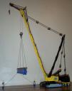
| | Finally, a shot of the crane being used to lift a large I-beam...
| | ...and configured for maximum height lift, at approx 145cm.
|
|
 |
Site last modified November 4, 2004 Home
|


