To LUGNET HomepageTo LUGNET News HomepageTo LUGNET Guide Homepage
 Help on Searching
 
To LUGNET News Traffic PageSign In (Members)
 Ross Crawford / projects / allterraincrane


Rosco’s LugNet Page

These pages are no longer updated. You can view my LEGO related pages here.

All images hosted by Brickshelf L.L.C. but who knows how long that will last.


All Terrain Crane

General View
   Based on the DEMAG AC100, this crane is larger scale than my other cranes. It’s not exactly to scale, but at about 1:32, it’s outside what most people consider “minifig scale”, even though minifigs look OK driving it.

I recently got a chance to see one up close, it was working near my home, so I took some photos.

This model also marks the first time I’ve used stickers on my MOCs - they didn’t turn out perfect, but they sure add a lot to the model!

Specifications

Carrier

Drive / Steer:
   10 x 6 x 8; fake planetary hubs on all driven axles
 
Outriggers:
   4 outrigger beams with jack legs
 
Axles:
   axle 1: steering; axle 2: driven, steering; axle 3: rigid axle, non-steer; axle 4: driven, steering; axle 5: driven, steering
 
Wheels and Tyres:
   10 Model Team wheels fitted with tyres; single wheels on all axles
 
Drivers Cab:
   Fully air-conditioned, easy opening, with 2 passenger seats (yes, they’re pink!)

Superstructure

Hoist:
   Manual hoist drum with 5:3 reduction and friction
 
Slew Unit:
   Technic turntable, allowing 360 degree rotation
 
Boom Elevation:
   BRE designed axle-hoist; string wound on reel with 3:1 reduction and friction
 
Crane Cab:
   Fully air-conditioned, tiltable
 
Main Boom:
   Boom base and 2 telescopic sections, 50cm - 110cm; manual extension
 
Counterweight:
   3 x 2x6x2 train weights

Optional Equipment

Drive / Steering:
   10 x 8 x 8
 
Dolly trailer:
   For transport on roads with lower axle limits, or when more than the standard counterweight is required
 
Main Boom Extension:
   Foldaway jib, 25cm, 0, 10, 20, 30 degree offset

Details

Carrier

The carrier has 2 main functions; the 4 outriggers, and steering on 4 axles.

The outriggers are just 1x10 bricks with 1x8 tile on top, and an extra 1x2 tile to stop them sliding out too far. They are able to carry the weight of the crane itself, but not much more, so I usually attach some bricks underneath the chassis to hold the crane up while working.
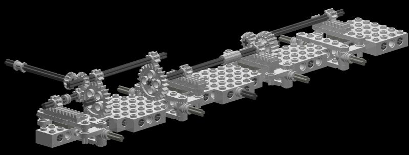
Steering detail

The steering geometry is not perfect, but it’s close. Axle 1 (front) turns 3 times further than 2 & 4, axle 5 turns 5/3 times further. To get the deck low enough, the 5:3 gears actually protrude up into the hole in the centre of the turntable! Note also the requirement to go “up and over” the outriggers between axles 1 and 2. This increased the backlash in the steering mechanism a little, but there was no other way around it. Note also that the steering control is on the side - I would have preferred the top, but the boom covers up too much of the top to allow it. Here is a view from underneath, with the wheels on full lock:

Undercarriage

The turntable is integrated into the carrier, and is not easily removable. There is also a V-8 engine, driver’s cab, and room for the standard counterweight.
   Carrier Greeblies

Superstructure

Elevating the boom
This is accomplished by sliding a 12L axle through a long block of 1x2 technic bricks. String is run through the bricks down one side of the axle, under it, and up the other side. One end of the string is tied, while the other is attached to a reel. Winding the reel pushes the axle out of the block, simulating a hydraulic ram.

There were a couple of problems with this approach:

1. The axle bends under load. This isn’t a big problem, just looks a bit strange.

2. As the axle can only slide a maximum of 10 studs, I had to attach it’s base closer to the base of the boom than I’d have liked. It’s still able to elevate the boom OK, but the geometry is all wrong. Maybe one day I’ll buckle and use one of John Barnes’ lead screws...

Close up of ram
   Elevating the boom


Extending the boom
This is done manually, by pulling the innermost boom section. There is string which pulls the centre section out at half the rate, and pushes it back in.

The discovery of how to do 2 telescopic sections in 4x4 cross section was the motivation for this crane. Here is an exploded pic of how it’s done:
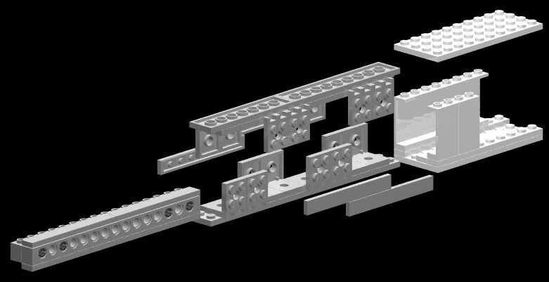
Boom Construction

An interesting attribute of the construction is that the centre section is symmetrical - 5 plates (2 studs) square internal, 9 plates (3 bricks) square external; so it fits fine at 90 degree rotation, too. This gives the option of having “studs out” on top & bottom, instead of “studs in” as I’ve done here.

It’s pretty rigid - you can see here a picture of it fully extended under load, and it doesn’t deflect as much as I thought it would. You can also see here one of the ropes used to synchronise the extension of the centre section. The other rope is totally enclosed inside the boom.
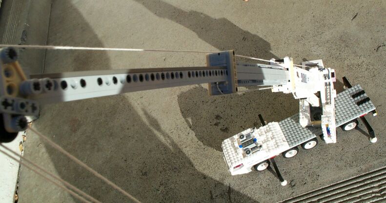
Under load

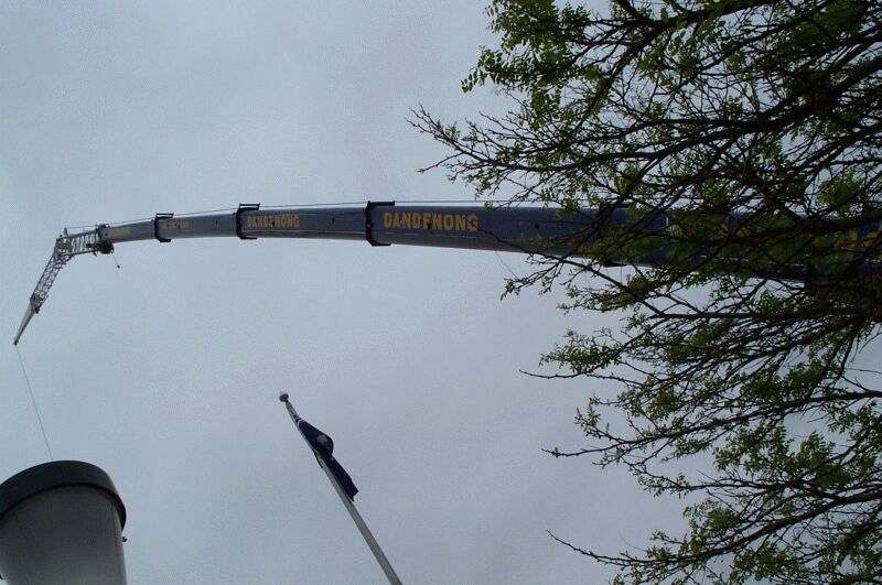
Compare this with the real thing:

Real booms deflect too!


Hoist
This is a simple reel made with gears on an axle. There is a hose reel providing friction, and a 5:3 reduction. The hook is sheaved as 3 part standard, but can easily be re-sheaved to 2 part.
3 part line2 part line

Counterweight
The crane can carry 3 train weights as standard, or just 2 (as seen here) for smaller lifts.
   Hoist

Cab
The cab can tilt to reduce neck strain on high lifts. Well placed simple controls make the crane a breeze to operate!
   Tilting cab

The superstructure can be removed easily by pulling out 4 pins, and gently prising it loose from the turntable. Looking closely at the carrier, you can just see the 20 tooth double-bevel gear which protrudes into the centre of the turntable.
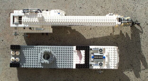
Two modules

Optional Equipment

The optional dolly trailer is designed to be towed by the crane, and carry the boom when travelling on roads with lower axle limits. It spreads some of the weight of the boom so it isn’t carried by the main axles. This also allows more counterweight to be carried if necessary.
   Trailer

The optional boom extension adds 25cm to the boom, and can be fixed at 0, 10, 20 or 30 degree offset. Because of the extra height, the hook must be re-sheaved as 2 part when using the extension.

Extension Step 1
Extension Step 2
Extension Step 3
   Boom extension

Load Test

And finally, I thought I’d see how much load it could actually lift. Following Jennifer Clark’s lead, I decided to use canned food, in this case a 700g can of dog food. The lift was successful, but unfortunately the friction of the hose reels holding the boom up wasn’t quite enough, so I had to lock it in place. Note how much the elevating axle bends. And you can see by the picture that the turntable was under a fair bit of strain - I probably needed more ballast to make such a heavy lift safely. Also to put this in perspective, it’s only about half the weight of crane itself - the real crane could lift the equivalent of over 3kg...

Anyhow, here are the pictures:

Lifting 700g
   Lifting 700g

Here’s the brickshelf gallery with more shots (after moderation).


Site last modified November 4, 2004 Home

Primary content in this document is © Ross Crawford. All other text, images, or trademarks in this document are the intellectual property of their respective owners.


©2005 LUGNET. All rights reserved. - hosted by steinbruch.info GbR