| |
Hi all.
I am currently working on a project (to be revealed in due course!) and I've
come across something of a stumbling block. I have a tray that is constrained to
move in one dimension, and a series of short liftarms under the tray, all
rotating in phase with each other, and placed such that once per rotation, they
connect with the tray (ok, so the tray can move vertically as well, but only a
little bit!) and move it along a specified distance. So far so good. What I need
is for the motor to change direction when the tray has reached the limit of its
travel, and to have such a mechanism at each end of the track, so the tray moves
back and forth for as long as power is supplied. Make sense?
Now, this would be trivial to do using a couple of sensors and a computer (RCX
or NXT or similar), but aside from the fact that I don't own any sensors for my
RCX, I have committed to using only electromechanical principles. Until now, I
have been trying to achieve this using a pole reverser switch, but have run into
the problem where the switch turns the motor off at the top of travel, and the
tray doesn't have enough momentum to finish the job itself. I have experimented
with using rubber bands/shock absorbers to make the natural state of the switch
either Forward or Reverse (kind of like the setup in the 8480 Space Shuttle,
where the natural state of the switch is Off), but I've found that this doesn't
actually help much - there is still enough dead space at the top of the switch
to cause problems.
So, my first question is can I use two switches, linked together such that
switch A is Forward when switch B is Off, and switch A is Off when switch B is
Reverse, similar to what the pneumatic fanatics do to eliminate dead space at
the top of a pneumatic switch (see
http://www.brickshelf.com/gallery/kclague/Computing/p6040061.jpg for an
example), or will I get into trouble with short circuiting stuff and blow
something up?
If that's a no-go, can anybody else suggest some mechanism to do what I need it
to do? Bearing in mind that the way the tray travels means that whatever trips
the switch is going to have to be very sensitive, because the tray is not going
to be able to push very hard against anything. The mechanism also needs to be
self-resetting. It would also be acceptable to have the motor running the same
direction all the time, but have the output diverted to a different shaft to
move the tray in the other direction.
Thanks in advance for any suggestions.
Owen.
|
|
| |
In lugnet.technic, Owen Dive wrote:
> Hi all.
SNIP
> Thanks in advance for any suggestions.
>
> Owen.
I have been asked for some pictures of what I am working on (very much
prototypes at the present - don't expect anything elegant).
http://www.brickshelf.com/gallery/captainowie/Decimator/picture_001.jpg
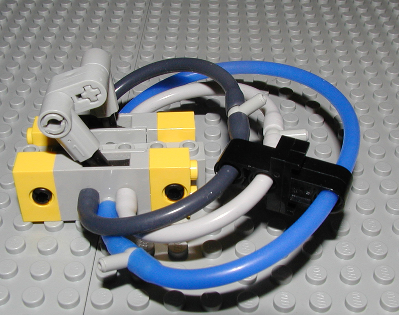
This is the track for the tray, and the drive mechanism. As the axle at the
front (bottom) of the device turns, the black liftarms pick up the tray and
carry it forward a distance of exactly two studs. They then leave the tray alone
for half their rotation, which is critical for the other part of the machine
(not relevant here). You can see the tray in the top corner.
http://www.brickshelf.com/gallery/captainowie/Decimator/picture_002.jpg
This is the track from a different angle, and the tray. The pins in the tray are
there to ensure that the liftarms have something to push against.
http://www.brickshelf.com/gallery/captainowie/Decimator/picture_003.jpg
Here you can see the tray in the track, at one limit of its travel.
Hope that helps to clear things up - keep the ideas flowing!
Owen.
|
|
| |
In lugnet.technic, Owen Dive wrote:
> Hi all.
>
> I am currently working on a project (to be revealed in due course!) and I've
> come across something of a stumbling block.
> Owen.
SNIP
I don't think there is a 'save' way to do that. In fact thats the reason
reversal switches have dead space, because you will short circuit stuff
otherwise (might be only for a millisecond though).
I don't know if you ever worked with some rudimentary electronics, but maybe you
could get what you want using a (set of) relays.
These kind of parts aren't usually very expensive at bigger hobby/electronics
store. And the internet is full of circuit plans.
Roland
|
|
| |
In lugnet.technic, Owen Dive wrote:
> Hi all.
>
> I am currently working on a project (to be revealed in due course!) and I've
> come across something of a stumbling block. I have a tray that is constrained to
> move in one dimension, and a series of short liftarms under the tray, all
> rotating in phase with each other, and placed such that once per rotation, they
> connect with the tray (ok, so the tray can move vertically as well, but only a
> little bit!) and move it along a specified distance. So far so good. What I need
> is for the motor to change direction when the tray has reached the limit of its
> travel, and to have such a mechanism at each end of the track, so the tray moves
> back and forth for as long as power is supplied. Make sense?
<snip>
Hi Owen,
As you say, you want a mechanism where the switch wants to be either on or
off, but not in the middle. Had you thought about adding a pivot point at the
top of the switch handle, with an axle going up and a weight at the top.
Imagine the right hand switch, switched to the left, and the pivot having the
weight directly above the pivot. The tray slides right, hits the axle, tipping
the weight to the right. There is a limit on the pivot, so the weight's
momentum then forces the switch to flip. Presuming you can do that, then all
you have to do is somehow get the weight back to the starting position.
This solution may not work, but it is worth a try. The word hysteresis comes
to mind, but I'm not sure that is really the case here. I know the problem well
though... Imagine a pneumatic piston flipping a pneumatic switch, but the
switch's outputs control the piston. Once you hit the off position everything
stops. Like you, I worked out a rubber band based mechanism where the switch
hated to be off:
http://www.kclague.net/oscillator/index.htm
But given you already found one of my other "no off" solutions, you probably
found this one as well.
Kevin
|
|
| |
In lugnet.technic, Kevin L. Clague wrote:
> In lugnet.technic, Owen Dive wrote:
> > Hi all.
> >
> > I am currently working on a project (to be revealed in due course!) and I've
> > come across something of a stumbling block. I have a tray that is constrained to
> > move in one dimension, and a series of short liftarms under the tray, all
> > rotating in phase with each other, and placed such that once per rotation, they
> > connect with the tray (ok, so the tray can move vertically as well, but only a
> > little bit!) and move it along a specified distance. So far so good. What I need
> > is for the motor to change direction when the tray has reached the limit of its
> > travel, and to have such a mechanism at each end of the track, so the tray moves
> > back and forth for as long as power is supplied. Make sense?
>
>
> <snip>
>
> Hi Owen,
> As you say, you want a mechanism where the switch wants to be either on or
> off, but not in the middle. Had you thought about adding a pivot point at the
> top of the switch handle, with an axle going up and a weight at the top.
>
> Imagine the right hand switch, switched to the left, and the pivot having the
> weight directly above the pivot. The tray slides right, hits the axle, tipping
> the weight to the right. There is a limit on the pivot, so the weight's
> momentum then forces the switch to flip.
Hmm, an interesting solution.
> Presuming you can do that, then all
> you have to do is somehow get the weight back to the starting position.
But there's the rub! I'm afraid I can't see an obvious way to do that, given
that the weight will need to be positioned quite precisely. I will play around
with it, though, and see what I can come up with.
> This solution may not work, but it is worth a try. The word hysteresis comes
> to mind, but I'm not sure that is really the case here. I know the problem well
> though... Imagine a pneumatic piston flipping a pneumatic switch, but the
> switch's outputs control the piston. Once you hit the off position everything
> stops. Like you, I worked out a rubber band based mechanism where the switch
> hated to be off:
>
> http://www.kclague.net/oscillator/index.htm
>
> But given you already found one of my other "no off" solutions, you probably
> found this one as well.
I had indeed found that one, but was put off by "Once the piston achieves the
strength to move the handle, the pressure built up in the piston makes it snap
into motion. That snap gives the valve enough momentum to make it beyond the
center of travel on the switch.". I'm not working with pneumatics, so I don't
have the advantage of storing potential energy in that way. If I could figure
out a way to introduce some delay into the system, so that whatever pushes the
switch continues for a short while after the motor stops, then I'd be set!
Thanks for your input.
Owen.
|
|
| |
In lugnet.technic, Owen Dive wrote:
> Hi all.
>
> I am currently working on a project (to be revealed in due course!) and I've
> come across something of a stumbling block. I have a tray that is constrained to
> move in one dimension, and a series of short liftarms under the tray, all
> rotating in phase with each other, and placed such that once per rotation, they
> connect with the tray (ok, so the tray can move vertically as well, but only a
> little bit!) and move it along a specified distance. So far so good. What I need
> is for the motor to change direction when the tray has reached the limit of its
> travel, and to have such a mechanism at each end of the track, so the tray moves
> back and forth for as long as power is supplied. Make sense?
>
> Now, this would be trivial to do using a couple of sensors and a computer (RCX
> or NXT or similar), but aside from the fact that I don't own any sensors for my
> RCX, I have committed to using only electromechanical principles. Until now, I
> have been trying to achieve this using a pole reverser switch, but have run into
> the problem where the switch turns the motor off at the top of travel, and the
> tray doesn't have enough momentum to finish the job itself.
Last year I built a pneumatic excavator module for a GBC display exactly for
this reason: doing it with an RCX would have been like cheating when it could be
done mechanically :D
As for your 'problem', I've been turning this over in my mind for some time and
for now the best solution I've come up with involves an extra switch and an
extra motor:
The tray should throw the switch for the extra motor which in turn will change
the switch for the tray. I'm still looking for a better solution though.
Jetro
|
|
| |
In lugnet.technic, Owen Dive wrote:
> In lugnet.technic, Owen Dive wrote:
> > Hi all.
>
> SNIP
> > Thanks in advance for any suggestions.
> >
> > Owen.
>
> I have been asked for some pictures of what I am working on (very much
> prototypes at the present - don't expect anything elegant).
>
> http://www.brickshelf.com/gallery/captainowie/Decimator/picture_001.jpg
> This is the track for the tray, and the drive mechanism. As the axle at the
> front (bottom) of the device turns, the black liftarms pick up the tray and
> carry it forward a distance of exactly two studs. They then leave the tray alone
> for half their rotation, which is critical for the other part of the machine
> (not relevant here). You can see the tray in the top corner.
>
> http://www.brickshelf.com/gallery/captainowie/Decimator/picture_002.jpg
> This is the track from a different angle, and the tray. The pins in the tray are
> there to ensure that the liftarms have something to push against.
>
> http://www.brickshelf.com/gallery/captainowie/Decimator/picture_003.jpg
> Here you can see the tray in the track, at one limit of its travel.
>
> Hope that helps to clear things up - keep the ideas flowing!
>
> Owen.
Ok, so I have something that appears to do what I need it to do, however, it is
a bit of a monstrosity, and I think that it shows either that I am a genius, or
a madman - I'm not sure which!
Bear in mind that this still includes several quick hacks to get the thing to
work - it's far from production quality.
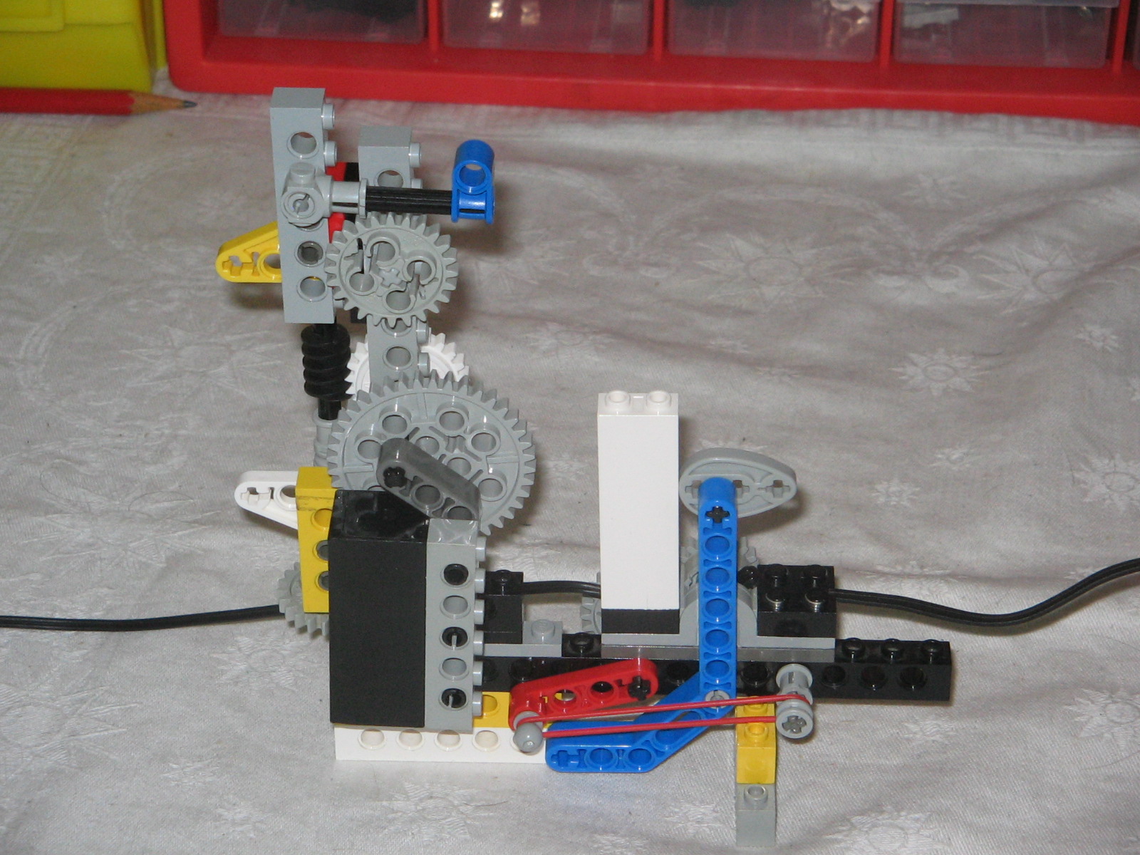
So. http://www.brickshelf.com/gallery/captainowie/Decimator/picture_004.jpg
and http://www.brickshelf.com/gallery/captainowie/Decimator/picture_005.jpg show
The Device primed and ready for action. The trigger is the blue axle joiner at
the top of the image. The grey connector on the same axle is blocking the
rotation of the 24t gear, which is in turn blocking the rotation of the 40t
gear. When the trigger is lifted, both gears begin moving due to the weight of
the black weight brick. This then falls with enough momentum to force the red
liftarm into the down position, flipping the switch at the same time.
http://www.brickshelf.com/gallery/captainowie/Decimator/picture_006.jpg and
http://www.brickshelf.com/gallery/captainowie/Decimator/picture_007.jpg show The
Device after this has happened. Now all you need to do is pull the blue angled
liftarm to make the elastic band pull the red liftarm back to its original
position, flipping the switch again.
Potential energy is supplied via the 24t gear at the bottom of the image (the
one in the horizontal plane), which drives the weight back to the top via the
worm gear/clutch gear pair.
Other things to note:
* The axle that the 40t gear is on does not go through the centre of the gear.
This allows the 40t gear to only mesh with the trigger-stop when the weight is
just past the top of its travel.
* The clutch gear allows the input to keep turning even when the weight is
blocked by the trigger.
* The freedom of the worm gear to move upwards allows the weight to fall
naturally, without being restricted by the input speed.
* The fact that the operation is assymetrical is no bad thing. The backwards
speed of the tray need not be limited by the necessarily slow forward speed - in
the same way that a typewriter carriage moves forward one letter space at a
time, but can be returned all at once.
* The tall white brick above the switch is there to guide the weight brick so
that it doesn't catch on any of the other bits, and the cam on the blue liftarm
is there to stop it (the liftarm) falling into the path of the weight.
Questions, comments or constructive criticism? My gut feeling is that the whole
thing is overcomplicated - however, that could fit in well with the rest of the
machine!
Thanks to everyone who has contributed, both in this thread and via email.
Owen.
|
|
| |
> I have been asked for some pictures of what I am working on (very much
> prototypes at the present - don't expect anything elegant). • ...
> Hope that helps to clear things up - keep the ideas flowing!
>
> Owen.
Well, seeing your pictures, I can't help wondering: do you actually need the
tray to change direction as soon as it hits the end?
If not, you can use a much easier solution: just power its motor for a given
amount of time in one direction, then the same amount of time in the other
direction, and so on. If your tray needs, say 14 seconds to move to one side,
just apply power for 16 or something.
The only drawbacks are that you need to be sure that it's not a problem to
continue to apply power when the tray is at the end (which you can do using a
clutch wheel although seeing your pics I don't even think you need anything);
and that the timing doesn't need to be too exact.
The advantage is that you don't need the power reversal mechanism to depend on
sensing anything - so that it just becomes a matter of having another motor
reverse polarity every x seconds.
I've used such a setup with one PF motor to drive a PF switch, which would
reverse regularly; the time between reversal being just a little more than what
another motor needs to drive a linear actuator from one end to the other. No
sensor needed, and the linear actuator just went back and forth.
I've also seen posts of someone doing this to power a back-and-forth train,
while diode-rails at the ends to stop it until the next power reversal. No need
for sensors or anything.
|
|
| |
In lugnet.technic, Jean-Marc Nimal wrote:
> > I have been asked for some pictures of what I am working on (very much
> > prototypes at the present - don't expect anything elegant). ...
> > Hope that helps to clear things up - keep the ideas flowing!
> >
> > Owen.
>
> Well, seeing your pictures, I can't help wondering: do you actually need the
> tray to change direction as soon as it hits the end?
>
> If not, you can use a much easier solution: just power its motor for a given
> amount of time in one direction, then the same amount of time in the other
> direction, and so on. If your tray needs, say 14 seconds to move to one side,
> just apply power for 16 or something.
>
> The only drawbacks are that you need to be sure that it's not a problem to
> continue to apply power when the tray is at the end (which you can do using a
> clutch wheel although seeing your pics I don't even think you need anything);
> and that the timing doesn't need to be too exact.
You're quite right in that there's nothing in the pictures to suggest that
having the having the motor running after the tray reaches its stop would be a
bad idea. However, that would be disastrous for the rest of the machine - think
of a typewriter where the keys continued to type after the carriage reached the
limit of travel. The machine would still function, but the result is not what
was intended.
In any case, I would like to avoid using an RCX if it is at all possible.
Thanks for your suggestion though.
Owen.
|
|
| |
In lugnet.technic, Owen Dive wrote:
> In lugnet.technic, Kevin L. Clague wrote:
<snip>
> Hmm, an interesting solution.
> > Presuming you can do that, then all
> > you have to do is somehow get the weight back to the starting position.
>
> But there's the rub! I'm afraid I can't see an obvious way to do that, given
> that the weight will need to be positioned quite precisely. I will play around
> with it, though, and see what I can come up with.
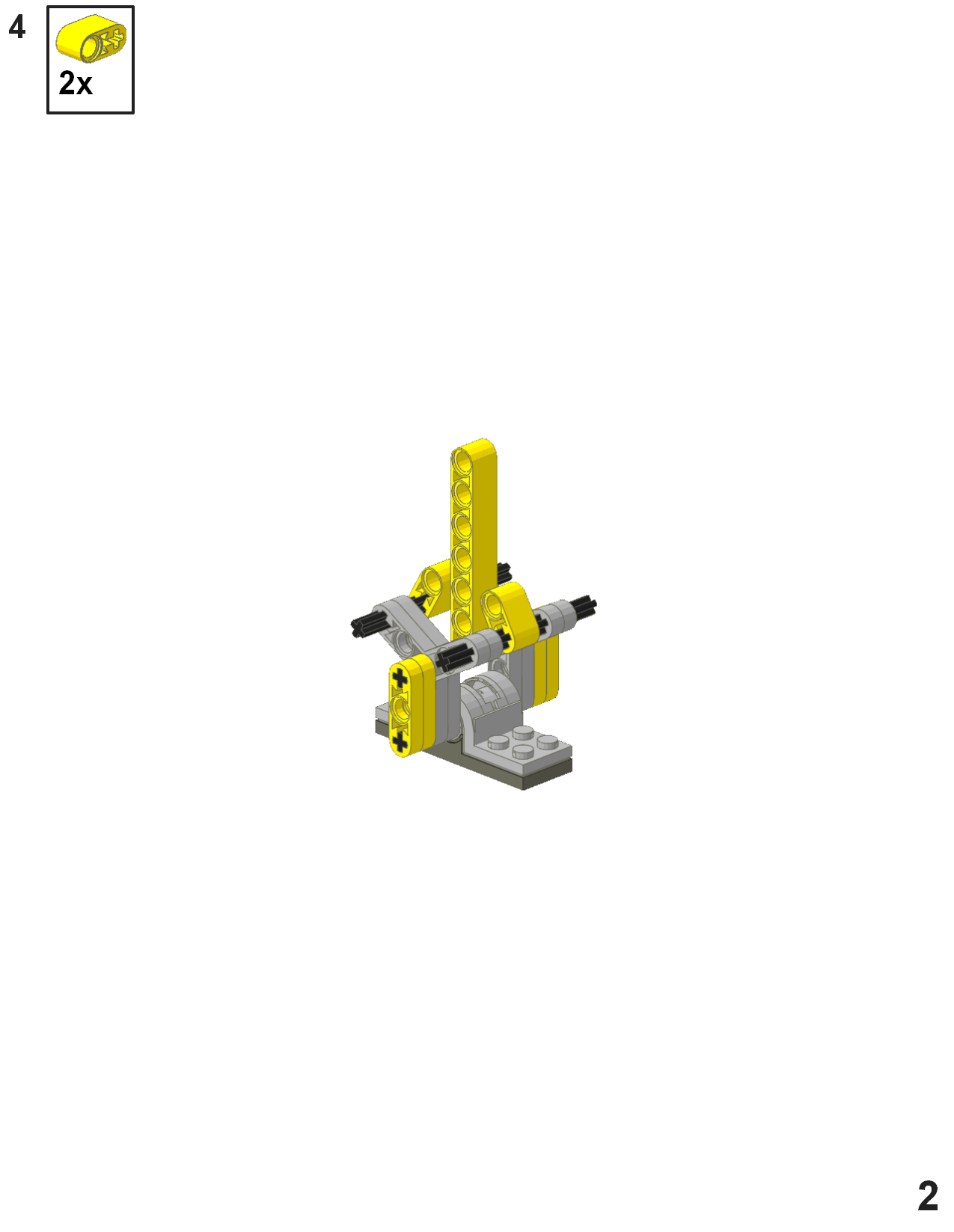
I've got a slightly different solution, where the tray tips an inverted pendulum
right and left. The pendulum's momentum/weight flip the polarity reverser.
The tri-blade bounds the inverted pendulum's swing.
The first three steps represent the basic inverted pendulum.
http://www.brickshelf.com/cgi-bin/gallery.cgi?i=4312628
The yellow beam added in step 2 is the inverted pendulum (on which you can add
your favorite weight attachment).
In step 4, you can limit the range of motion of the inverted pendulum (if you
wish). Other limiting devices (8T gear, 1/2 bushing, etc.) can be used instead.
http://www.brickshelf.com/cgi-bin/gallery.cgi?i=4312629
I don't know if the tray's slow progression right and left can eventually tip
the inverted pendulum past center (it depends on if the inverted pendulum can
reverse the tray's travel)..... but if it can it might help.
Kevin
|
|
| |
In lugnet.technic, Kevin L. Clague wrote:
> In lugnet.technic, Owen Dive wrote:
> > In lugnet.technic, Kevin L. Clague wrote:
>
> <snip>
>
> > Hmm, an interesting solution.
> > > Presuming you can do that, then all
> > > you have to do is somehow get the weight back to the starting position.
> >
> > But there's the rub! I'm afraid I can't see an obvious way to do that, given
> > that the weight will need to be positioned quite precisely. I will play around
> > with it, though, and see what I can come up with.
>
> I've got a slightly different solution, where the tray tips an inverted pendulum
> right and left. The pendulum's momentum/weight flip the polarity reverser.
>
> The tri-blade bounds the inverted pendulum's swing.
>
> The first three steps represent the basic inverted pendulum.
>
> http://www.brickshelf.com/cgi-bin/gallery.cgi?i=4312628
Direct access:
http://www.brickshelf.com/gallery/kclague/fun/fun_page_1.png
>
> The yellow beam added in step 2 is the inverted pendulum (on which you can add
> your favorite weight attachment).
>
> In step 4, you can limit the range of motion of the inverted pendulum (if you
> wish). Other limiting devices (8T gear, 1/2 bushing, etc.) can be used instead.
>
> http://www.brickshelf.com/cgi-bin/gallery.cgi?i=4312629
Direct access:
http://www.brickshelf.com/gallery/kclague/fun/fun_page_2.png
>
> I don't know if the tray's slow progression right and left can eventually tip
> the inverted pendulum past center (it depends on if the inverted pendulum can
> reverse the tray's travel)..... but if it can it might help.
>
> Kevin
Kevin
|
|
| |
In lugnet.technic, Kevin L. Clague wrote:
> In lugnet.technic, Kevin L. Clague wrote:
> > In lugnet.technic, Owen Dive wrote:
> > > In lugnet.technic, Kevin L. Clague wrote:
> >
> > <snip>
> >
> > > Hmm, an interesting solution.
> > > > Presuming you can do that, then all
> > > > you have to do is somehow get the weight back to the starting position.
> > >
> > > But there's the rub! I'm afraid I can't see an obvious way to do that, given
> > > that the weight will need to be positioned quite precisely. I will play around
> > > with it, though, and see what I can come up with.
> >
> > I've got a slightly different solution, where the tray tips an inverted pendulum
> > right and left. The pendulum's momentum/weight flip the polarity reverser.
> >
> > The tri-blade bounds the inverted pendulum's swing.
> >
> > The first three steps represent the basic inverted pendulum.
> >
> > http://www.brickshelf.com/cgi-bin/gallery.cgi?i=4312628
>
> Direct access:
>
> http://www.brickshelf.com/gallery/kclague/fun/fun_page_1.png
>
> >
> > The yellow beam added in step 2 is the inverted pendulum (on which you can add
> > your favorite weight attachment).
> >
> > In step 4, you can limit the range of motion of the inverted pendulum (if you
> > wish). Other limiting devices (8T gear, 1/2 bushing, etc.) can be used instead.
> >
> > http://www.brickshelf.com/cgi-bin/gallery.cgi?i=4312629
>
> Direct access:
>
> http://www.brickshelf.com/gallery/kclague/fun/fun_page_2.png
>
> >
> > I don't know if the tray's slow progression right and left can eventually tip
> > the inverted pendulum past center (it depends on if the inverted pendulum can
> > reverse the tray's travel)..... but if it can it might help.
> >
> > Kevin
>
> Kevin
A nice solution, but I doubt very much if my tray could push the pendulum
upright (especially since the total angular travel would be the limited movement
of the pendulum _plus_ the angle that the tri-blades had rotated). However, for
situations with more force available (e.g. a tray propelled by gears meshing
with a long rack**) it would work very well. I shall keep it in mind for future
projects!
Thanks!
Owen.
** I did experiment with this kind of set-up, but couldn't find a way to make
the tray travel two studs exactly (5 teeth of a rack) and then pause for a bit.
|
|
| |
In lugnet.technic, Owen Dive wrote:
| |
So, my first question is can I use two switches, linked together such that
switch A is Forward when switch B is Off, and switch A is Off when switch B is
Reverse, similar to what the pneumatic fanatics do to eliminate dead space at
the top of a pneumatic switch (see
http://www.brickshelf.com/gallery/kclague/Computing/p6040061.jpg for an
example), or will I get into trouble with short circuiting stuff and blow
something up?
|
It would depend on how much of the dead band you eliminate. Cleaning up
bookmarks I came a cross this which might work:
http://staff.science.uva.nl/~leo/lego/motorswitch.html

Jetro
|
|
| |
Here is yet another possible solution that I have found effective for something
very similar (a vehicle that reverses its direction when it hits an obstacle).
This one is purely mechanical (no electrical switch needed).
<http://www.youtube.com/watch?v=XP4zhMS79Ng#t=0m31s>
<http://www.brickshelf.com/cgi-bin/gallery.cgi?i=2300300>
The mechanism relies on the four 24t gears that you see. The left and right
ones are powered by the motor, and turn in opposite directions, towards the
centre (the left one clockwise and the right one anticlockwise). The bottom
gear is connected to the output (the wheels of the vehicle). The top gear
meshes with the bottom one and is free to pivot left or right (controlled by the
bumpers), determining which way the output turns.
Because the pivoting gear is above its pivot point, it is unlikely to stop in
the dead-centre disengaged position. And the direction of rotation means that
once in the left or right position, it is held there fairly firmly.
|
|
| |
In lugnet.technic, Alexander Holroyd wrote:
> Here is yet another possible solution that I have found effective for something
> very similar (a vehicle that reverses its direction when it hits an obstacle).
> This one is purely mechanical (no electrical switch needed).
>
> <http://www.youtube.com/watch?v=XP4zhMS79Ng#t=0m31s>
> <http://www.brickshelf.com/cgi-bin/gallery.cgi?i=2300300>
>
> The mechanism relies on the four 24t gears that you see. The left and right
> ones are powered by the motor, and turn in opposite directions, towards the
> centre (the left one clockwise and the right one anticlockwise). The bottom
> gear is connected to the output (the wheels of the vehicle). The top gear
> meshes with the bottom one and is free to pivot left or right (controlled by the
> bumpers), determining which way the output turns.
>
> Because the pivoting gear is above its pivot point, it is unlikely to stop in
> the dead-centre disengaged position. And the direction of rotation means that
> once in the left or right position, it is held there fairly firmly.
Hmm, I had dabbled with a similar solution, but inverted (with the motor driving
the bottom gear and the two side gears the two outputs, but discarded it for
reasons that escape me at the moment. I must investigate this further.
Thanks!
Owen.
|
|
| |
> Hmm, I had dabbled with a similar solution, but inverted (with the motor driving
> the bottom gear and the two side gears the two outputs, but discarded it for
> reasons that escape me at the moment. I must investigate this further.
Yes, there are quite a few possible variations on this mechanism. There is even
at least one in an official model:
<http://www.peeron.com/inv/sets/4895-1>
Hope you get it working. I always like a purely mechnical solution :)
|
|
| |
In lugnet.technic, Owen Dive wrote:
> Hi all.
>
> I am currently working on a project (to be revealed in due course!)
SNIP
> Thanks in advance for any suggestions.
>
> Owen.
So I bet you had all been waiting with bated breath for the revelation of my
project, and then I bet you had all thought that I had given up, when there was
no revelation forthcoming.
In actual fact, I had been working on this until I finished it in mid-December
last year, and I've just spent the last month or so putting together a
comprehensive write-up, which you can find here
http://www.lugnet.com/~2801/Decimator (almost 3800 words, 6 animated GIFs and
one photograph).
Questions, comments, queries or concerns, please let me know what you think!
Owen.
|
|
| |
Owen Dive wrote:
> In actual fact, I had been working on this until I finished it in
> mid-December last year, and I've just spent the last month or so
> putting together a comprehensive write-up, which you can find here
> http://www.lugnet.com/~2801/Decimator (almost 3800 words, 6 animated
> GIFs and one photograph).
Cool!
(You may be mad, but only in the very best way. ;-)
Play well,
Jacob
--
Classic racing car (with building instructions):
http://lego.sparre-andersen.dk/Transport/Biler/Veteranbil/
|
|
|