|
|
| |
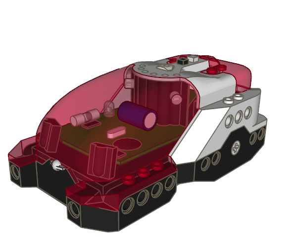
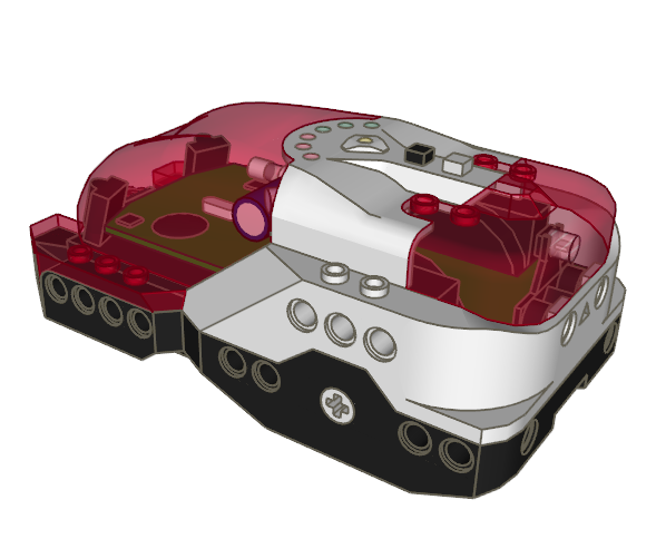
Linmix once said to me that he couldn’t find a LDraw model of the
Spybotics... so I decided to cope with
that beast.
Here is the prevue:
The LDraw files are available from
LDraw Parts
Tracker. Don’t forget all the subfiles!
Some LDrawers may wonder how I created the smooth front cover shape. I started
with a few hires 1-4edges, inlined them and modified their horizontal alignment
with MLCad:
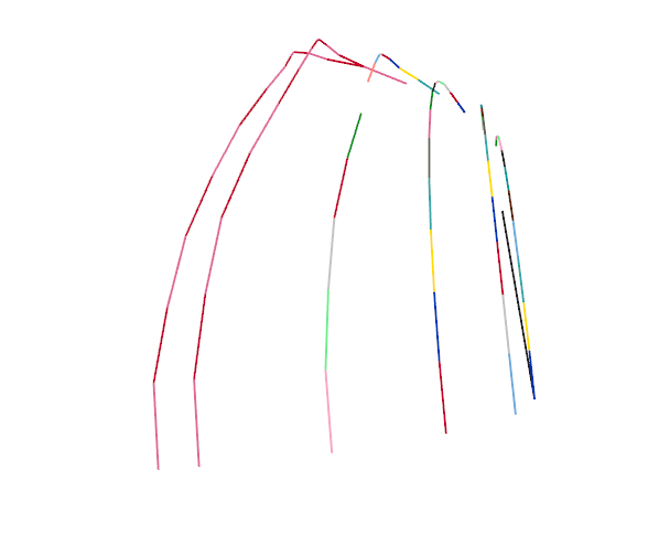
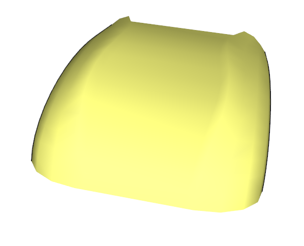
Then I created stripes of polygons between each pairs of lines using
Coverer tool.

Missing conditional lines between the stripes were created using Lee Gaiteri’s
Edger to obtain the nice smooth
shape (using LDView “smooth curves” option).
Enjoy,
Philo
|
|
| |
In lugnet.robotics.spybotics, Daniel Wittenaar wrote:
> Based on some code i found around here from John Barnes i rewrote his RCX2Manas
> control.
>
> Now it is cappable to control 3 manas units from 1 single spybot.
!
Then I will add two Spybotics nodes in to the 6 Mana/Legged robot I am building.
When I complete it would someone like to program it?
e
|
|
| |
I'm sorry for pulling up such old post.
But i'm a regular spybot & bascom user too.. And i'm busy at the moment with the
same project. Maybe we can help eachother..
I'm also very intressted in the VLL source code in Bascom..
Daniel Wittenaar
Brickbash Robotics
|
|
| |
Based on some code i found around here from John Barnes i rewrote his RCX2Manas
control.
Now it is cappable to control 3 manas units from 1 single spybot.
The next NQC code drives the motors of all of them just for demo..
You can build your own motor control scheme by calling the specific motor (em1 -
em6) Followed by EM_OFF, EM_FWD, EM_REV or EM_FLOAT.
Don't forget if you have the motors set to call 'task manas()'
Hopefully it will come handy for somebody.
Greetings,
Daniel Wittenaar
Brickbash Robotics
www.brickbash.nl
//Copyright by John Barnes making this programm for RCX use.
//Editted by Daniel Wittenaar - Brickbash Robotics for Spybotic use.
//For more information about the manas protocol go to
http://news.lugnet.com/robotics/?n=15809
#define MANAS_1 5
#define MANAS_2 6
#define MANAS_3 7
#define EM_FLOAT 0
#define EM_OFF 8
#define EM_FWD 7
#define EM_REV 15
int em1,em2,em3,em4,em5,em6; //Global motor control locations
task main()
{
// This demo starts the manas comms task, then loops forever.
// In the loop, it steps through three control phases setting
// the motors to off, and then paired forward and reverse.
start manas;
while (true)
{
em1=EM_OFF;
em2=EM_OFF;
em3=EM_OFF;
em4=EM_OFF;
em5=EM_OFF;
em6=EM_OFF;
Wait(100);
em1=EM_FWD;
em2=EM_REV;
em3=EM_FWD;
em4=EM_REV;
em5=EM_FWD;
em6=EM_REV;
Wait(100);
em1=EM_REV;
em2=EM_FWD;
em3=EM_REV;
em4=EM_FWD;
em5=EM_REV;
em6=EM_FWD;
Wait(100);
}
}
// The manas task continuously resends the motor settings.
// When the Spybotic is halted, this task stops and the manas
// motors automatically shut off
task manas()
{
while (true)
{
// First ensure serial settings are still ok
SetSerialType(SERIAL_TYPE_USER);
SetSerialBaud(SERIAL_BAUD_4800);
SetSerialChannel(SERIAL_CHANNEL_IR);
SetSerialChecksum(SERIAL_CHECKSUM_SUM);
// Set the first unit two message bytes and send them
SetSerialData(0,MANAS_1*0x10+em1);
SetSerialData(1,em2*0x10+0x10-((MANAS_1+em1+em2)&0xf));
SendSerial(0,2);
// Set the second unit two message bytes and send them
SetSerialData(0,MANAS_2*0x10+em3);
SetSerialData(1,em4*0x10+0x10-((MANAS_2+em3+em4)&0xf));
SendSerial(0,2);
// Set the third unit two message bytes and send them
SetSerialData(0,MANAS_3*0x10+em5);
SetSerialData(1,em6*0x10+0x10-((MANAS_3+em5+em6)&0xf));
SendSerial(0,2);
// Delay for a while so we can resend them regularly
Wait(10);
}
}
|
|
| |
In lugnet.robotics.spybotics, Joe Strout wrote:
| |
In lugnet.robotics.spybotics, Steve Hassenplug wrote:
| |
On Thu, November 3, 2005 12:14 pm, Joe Strout wrote:
| |
It occurred to me that one might fit some sort of light sensors on top of
some of the six LEDs on the Spybot’s top side, and use this to select an
input channel to route information from any of a number of sensors to the
VLL sensor.
Has anybody tried this yet? Any thoughts on how well this would work, or
pointers to a suitable multiplexer circuit?
|
You can control the VLL output of the spybot, so you should be able to just
connect something much like the programming cable, and get two-way
communications.
|
Two-way communications with what? Are you picturing some sort of
microcontroller that monitors all the extra sensors, and reports values to
the Spybot upon request?
That sounds beyond my capabilities, as well as probably not as fast as the
multiplexer approach. With the latter, to read (say) one of sixteen inputs,
you just set the four LEDs to address the desired input, then take a reading
from the VLL.
To communicate with a microcontroller, you’d instead have to send the
request, then wait for a reply, both using a serial protocol. I imagine that
for some applications, polling the sensors as fast as possible would be
helpful -- but I haven’t actually done the math, so maybe this isn’t actually
relevant.
| |
Here’s a good VLL page:
http://www.elecbrick.com/lego/
|
Thanks — I’d seen that before, but hadn’t realized its relevance to
Spybotics. Hmm... that suggests all sorts of fun things one might do, like
printing VLL codes onto a transparent wheel which you then spin in front of a
light (using a standard LEGO motor), making a “beacon” that not only
advertises its presence but transmits information (identity or commands) too.
Best,
- Joe
|
Some time ago, I have sugested the use of the VLL port to make an interface to
connect a couple of lego light sensors to the spybot. The ideea was to have an
analog device (powered by a 9V bov) that would just switch on a sensor, then
switch it off and turn on a LED that would shine proportional with the amount of
light sensed by the light sensor. This LED would be connected to the spybot’s
light sensor, which in turn would make the spybot light sensor sense about the
same light intensity as the Lego light sensor. Now using the spybots LED from
the VLL port, and having a fototransistor connected to it, it can trigger a gate
to select which Lego light sensor would be read. I hope it makes sense...
After playing with other microcontrollers, I just realised that this aproach is
too complicated. A simple 8 pin PIC would do the trich much easier and is not
more expensive. I did not built it yet. Other projects got in the way, but
eventualy I will build one.
Gabe
|
|
| |
In lugnet.robotics.spybotics, John Hansen wrote:
> It is possible if you are really clever to write an
> NQC program which cooperates with the built-in ROM tasks and subroutines.
I spent some time recently working on NQC headers which would enable using more
(if not all) of the Spybot ROM subroutines and tasks with a NQC program. I
haven't done extensive testing of the headers in real programs. I hope there
are still a few Spybot users out there who might be willing to test them a bit
more than I have. There are 4 header files:
SpyGlobals.nqh
SpyInteraction.nqh
SpyBeads.nqh
SpyEvents.nqh
SpyGlobals.nqh includes SpyInteraction.nqh and SpyBeads.nqh. The header files
make use of the NQC preprocessor quite a bit to make sure that global variables
are correctly reserved and defined. The SpyEvents header file also hooks up a
special spybot event initialization routine. You can get these headers at
http://bricxcc.sourceforge.net/spynqh.zip. If you test them please let me know
if you run into any problems.
I also have a port of the Mindscript code for the Task 0 program in ROM to NQC
in the file builtin.nqc. Here it is:
#include "SpyGlobals.nqh"
#include "SpyEvents.nqh"
#define right 0 // output 1
#define left 1 // output 2
#define cAdvance 1
#define cRetreat 2
//int nMode;
#pragma reserve 9
#define nMode (@9)
task main()
{
// initialize our global variable
nMode = cAdvance;
SetPriority(2);
ResetMotors();
ResetEngine();
nStatus |= EVENT_RUNBEADS;
SetAnimation(ANIMATION_SCAN);
repeat(2)
{
PlayTone(2232, 10); Wait(20);
PlayTone(1736, 10); Wait(20);
PlayTone(1202, 10); Wait(35);
PlayTone(1202, 10); Wait(20);
PlayTone(1736, 10); Wait(20);
PlayTone(2232, 10); Wait(35);
}
SetLED(LED_MODE_ON, 0);
ResetMessages();
start MyPostWatcher;
// StartTask(cBuiltInPostWatcher);
start MyBumpWatcher;
// StartTask(cBuiltInBumpWatcher);
while(true)
{
SelectTarget();
if (Target(SPY_RANGE) > RANGE_ANYWHERE)
{
if (nMode == cAdvance)
{
if (Target(SPY_RANGE) == RANGE_THERE)
PlaySound(SOUND_MAGNET);
Advance_Bead(RANGE_HERE, 100);
}
else
{
if (Target(SPY_RANGE) == RANGE_HERE)
PlaySound(SOUND_REPULSE);
Retreat_Bead(RANGE_HERE, 100);
}
}
else
{
BasicMovement_Bead(MOVE_BASIC_SPIN_LEFT, 50);
Fx_Bead(FX_TWITTER, 25);
RandomMovement_Bead(MOVE_RANDOM_FORWARD, 100);
FancyMovement_Bead(MOVE_FANCY_BUG_FORWARD, 1, 100);
Wait(25);
}
}
}
task BumpWatcher()
{
}
task PowerUpTask()
{
int nLevel = EEPROM(EEPROM_USERLEVEL);
SetLED(LED_MODE_YELLOW, 0);
Wait(50);
if (nLevel < 16)
{
nStatus = EVENT_RUNBEADS;
CountDown_Bead(nLevel, COUNT_DIR_UP, 50);
}
ResetMotors();
Wait(100);
}
task MyPostWatcher()
{
while (true)
{
monitor(EVENT_MASK(PostEvent))
{
Wait(32767);
}
catch
{
SetPriority(0);
if ((RxMessageChannel() & MSG_IR) > 0)
{
SetRxMessageLock(MSG_IR);
if (RxMessage(MSG_IR, MSG_COMMAND) == COMMAND_CONTROLLER)
{
nControllerButton = RxMessage(MSG_IR, MSG_HI_BYTE);
nControllerButton *= 256;
nControllerButton |= RxMessage(MSG_IR, MSG_LO_BYTE);
}
switch(nControllerButton)
{
case CONTROLLER_BUTTON1:
PlayTone(3401, 3);
nMode = cAdvance;
break;
case CONTROLLER_BUTTON2:
Fire_Bead(CMD_FIRE_LASER,FIRE_TYPE_THERE_NARROW,-1,0,0,SOUND_FIRE_LASER,50);
break;
case CONTROLLER_BUTTON3:
PlayTone(2801, 3);
nMode = cRetreat;
break;
}
SetRxMessageLock(MSG_NONE);
}
}
}
}
task MyBumpWatcher()
{
while (true)
{
monitor(EVENT_MASK(BumpEvent))
{
Wait(32767);
}
catch
{
SetPriority(1);
PlaySound_Bead(SOUND_OUCH, 0);
BasicMovement_Bead(MOVE_BASIC_BACKWARD, 50);
BasicMovement_Bead(MOVE_BASIC_SPIN_RIGHT, 50);
}
}
}
|
|
| |
In lugnet.robotics.spybotics, Steve Hassenplug wrote:
| |
On Thu, November 3, 2005 12:14 pm, Joe Strout wrote:
| |
It occurred to me that one might fit some sort of light sensors on top of
some of the six LEDs on the Spybot’s top side, and use this to select an
input channel to route information from any of a number of sensors to the VLL
sensor.
Has anybody tried this yet? Any thoughts on how well this would work, or
pointers to a suitable multiplexer circuit?
|
You can control the VLL output of the spybot, so you should be able to just
connect something much like the programming cable, and get two-way
communications.
|
Two-way communications with what? Are you picturing some sort of
microcontroller that monitors all the extra sensors, and reports values to the
Spybot upon request?
That sounds beyond my capabilities, as well as probably not as fast as the
multiplexer approach. With the latter, to read (say) one of sixteen inputs, you
just set the four LEDs to address the desired input, then take a reading from
the VLL.
To communicate with a microcontroller, you’d instead have to send the request,
then wait for a reply, both using a serial protocol. I imagine that for some
applications, polling the sensors as fast as possible would be helpful -- but I
haven’t actually done the math, so maybe this isn’t actually relevant.
| |
Here’s a good VLL page:
http://www.elecbrick.com/lego/
|
Thanks — I’d seen that before, but hadn’t realized its relevance to Spybotics.
Hmm... that suggests all sorts of fun things one might do, like printing VLL
codes onto a transparent wheel which you then spin in front of a light (using a
standard LEGO motor), making a “beacon” that not only advertises its presence
but transmits information (identity or commands) too.
Best,
- Joe
|
|
| |
On Thu, November 3, 2005 12:14 pm, Joe Strout wrote:
> It occurred to me that one might fit some sort of light sensors on top of some
> of the six LEDs on the Spybot's top side, and use this to select an input
> channel to route information from any of a number of sensors to the VLL sensor.
>
> Has anybody tried this yet? Any thoughts on how well this would work, or
> pointers to a suitable multiplexer circuit?
You can control the VLL output of the spybot, so you should be able to just connect
something much like the programming cable, and get two-way communications.
Here's a good VLL page:
http://www.elecbrick.com/lego/
Steve
|
|
| |
It occurred to me that one might fit some sort of light sensors on top of some
of the six LEDs on the Spybot’s top side, and use this to select an input
channel to route information from any of a number of sensors to the VLL sensor.
Has anybody tried this yet? Any thoughts on how well this would work, or
pointers to a suitable multiplexer circuit?
Thanks,
– Joe
|
|
| |
In lugnet.robotics.spybotics, Joe Strout wrote:
| |
I’ll keep y’all posted on my progress, so if somebody else comes along later
in the same boat, they can learn from my mistakes!
|
Well, here’s one: don’t buy a Dynex USB-to-serial adapter. The packaging and
web site both claim it’s Mac compatible, but I tried it on two different
machines (a G4 Powerbook running 10.2.8 and a dual G5 desktop running 10.3.9),
and two different serial apps (MacNQC and an app I wrote myself a while back to
test serial devices), and neither one sees this Dynex gadget as a serial port at
all.
I called Dynex tech support, and they were very nice, but utterly unhelpful.
Their answer amounted to, “It should just work.” Well, it doesn’t.
Everything I read indicates that the Keyspan ‘USA-19HS’ is the right gizmo to
use. It’s a bit hard to find in the stores — I’m going to have to order mine
online — but I bet it will work reliably. More later when I have positive
results.
Best,
– Joe
|
|
|